Before assembly, lubricate all gearbox parts to prevent scoring during the initial period of operation
Before installing, lubricate the threaded part of the bolts with paint
Only new gaskets and seals are installed during assembly.
Assemble the gearbox in the reverse order of disassembly. In this case, the following must be taken into account.
Assemble the drive shaft and third gear with the synchronizer locking rings.
During assembly, the following must be ensured:
- - the contact area of the ring to the shaft is not less than 70% of the surface of the drive shaft cone;
- - the gap between the ends of the straight-toothed crown of the drive shaft and the locking ring is within 0.8-1.25 mm;
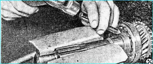
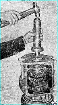
- - if necessary, grind the conical surfaces of the shaft and ring; tighten the drive shaft ball bearing fastening nut (torque 30 kgm) and punch it over the shaft groove (Fig. 1).
Match the first and reverse sliding gear with the splines of the driven shaft.
The match should ensure that there is no noticeable angular play when the gear slides freely along the shaft splines.
Angular the clearance on the splines should be no more than 0.18 mm when checking on the radius of the pitch circle of the gear.
The axial clearance of the first gear and reverse gear on the shaft during selection should be no more than 0.05 mm when measured on a radius of 75 mm.
After selection, mark the location of the splines of the mating parts with paint.
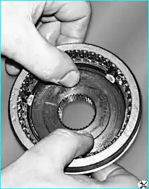
Select the coupling according to the splines of the synchronizer hub. This selection should ensure:
- - lateral clearance within 0 — 0.01 mm and easy movement of parts without noticeable lateral clearance;
- - longitudinal clearance of the coupling in its extreme positions is no more than 0.2 mm and runout of the ends of the groove for the shift fork is no more than 0.18 mm when checked on a splined mandrel
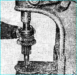
Fig. 2 shows the installation of crackers and synchronizer spring, and Fig. 3 — pressing the sliding clutch with the hub onto the driven shaft
When assembling the head of the reverse gear rod, screw the spring stopper flush with the end of the housing and punch it at four points.
Press the reverse gear block axle flush with the surface of the rear wall of the crankcase.
Install the block axle so that if you look at the end of the axle from behind (in the direction of the car), its chamfers would be facing the intermediate shaft and would be located symmetrically relative to the horizontal axis of the block.
On some cars, there are no chamfers.
Press the plug of the front bearing of the intermediate shaft on the sealing paste flush with the front wall of the crankcase.
Tighten the intermediate shaft ball bearing fastening nut (torque 25 kgm) and punch it over the shaft groove.
Pressing in this bearing is shown in Fig. 4.
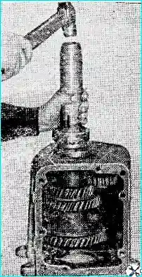
When installing the drive shaft (Fig. 5) into the gearbox housing hole, ensure that the recess on the straight-toothed crown and shaft cone is at the bottom.
Press the driven shaft oil seal flush with the outer end of the cover.
Tighten the flange fastening nut on the driven shaft (torque 25 kgm).
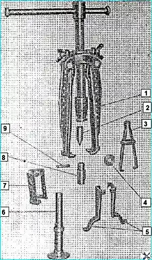
The tool for assembling and disassembling the gearbox is shown in rice. 6.
Place the assembled gearbox on a stand and test it without load at a rotation speed of 750 rpm of the driven shaft for one minute without adding oil for noise, heating and ease of shifting in all gears.
Installing the gearbox on the car
Using a lifting device, install the gearbox on the clutch housing.
Install the ventilation hatch on the right side of the clutch housing.
Install the clutch bearing oil cap (the bearing assembly with the coupling and the oil cap hose is installed before installing the gearbox).
Install the clutch release fork.
Install and cotter pin the clutch release fork rod.
Install the fork return spring.
Adjust the length clutch release fork rods.
Install the handbrake lever assembly.
Connect the handbrake rod to the lever on the gearbox,
Adjust the handbrake.
Secure the intermediate support of the propeller shaft.
Connect the flanges of the propeller shaft and the driven shaft of the gearbox.
Attach the speedometer drive cable.
Fill the gearbox with oil.
Install the transmission cover.
Install the gearbox control lever.
Install the protective cap of the upper cover.
Install the floor mat of the cabin.
The gearbox is installed on the GAZ-b6 vehicle in the reverse order of its removal.