The cardan transmission (Fig. 1) of the GAZ-53A vehicle consists of two shafts: intermediate 13 and main 10
The intermediate cardan shaft is a thin-walled pipe (inner diameter 71 mm, wall thickness 2.1 mm), at the front end of which there is a cardan shaft ending in a flange, and at the rear end there is a splined sleeve.
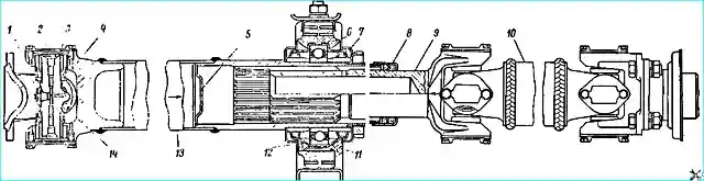
The intermediate shaft is fastened to the vehicle with bolts at the front by the cardan flange to the flange of the driven shaft of the gearbox, and at the rear by the bracket of the intermediate support to the cross member of the frame
The rear end of the intermediate shaft rotates in a ball bearing 12 (GPZ-114), placed in an elastic rubber cushion that absorbs vibration loads from the cardan transmission.
The main cardan shaft is a thin-walled pipe, at the front end of which there is a cardan shaft ending with a sliding splined fork, and at the rear - a cardan shaft ending with a flange.
The main shaft is fastened as follows: the front end engages with the splined sleeve of the intermediate shaft by means of a splined fork, and the rear end - with a bolted connection of the cardan flange to the flange of the drive pinion shaft of the main transmission of the rear axle.
The cardan transmission (Fig. 2) of the GAZ-66 vehicle consists of three shafts: intermediate, front and rear.
The front and rear shafts of the GAZ-66 are absolutely identical and differ only in the length between the cardans when installed on the vehicle due to the sliding spline connection.
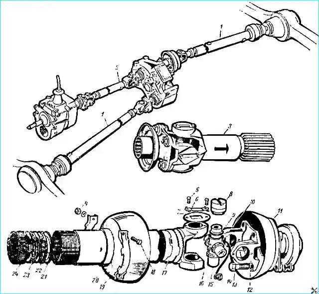
The cardan shafts located on the side of the drive axles on the GAZ-66 vehicle have protective stamped caps 11 and 19, which protect the cardan shafts from dirt and water.
All removable or wearing parts that make up the cardan transmissions of the GAZ-6b and GAZ-53A vehicles are interchangeable.
These include crosspieces, GPZ-804704K needle bearings, flanges, splined and sliding bushings, seal cages, seals, etc.
The intermediate support of the cardan shaft of the GAZ-53A vehicle (bearing, rubber cushion, felt seals) is unified with the vehicle ZIL-1Z0.
Propeller shaft maintenance
Propeller shaft maintenance consists of:
- - periodic lubrication of the cardan shafts, intermediate support bearing and changing the grease in the splined connection;
- - checking the fastening of the intermediate support bracket to the frame crossmember and the fastenings of the cardan shaft flanges to the gearbox and rear axle;
- - checking the tightening of the sliding fork oil seal cage;
- - checking the play in the cardan shafts, splined connection and intermediate support bearing (only on GAZ-53A);
- - cleaning the shafts from dirt.
Lubricate the cardan shaft needle bearings through grease nipples screwed into the crosspieces only transmission oil. It is unacceptable to lubricate them with consistent lubricants (such as solidol).
The bearing of the intermediate support of the GAZ-53A propeller shaft should be lubricated with consistent grease through the grease nipple located at the rear in the lower part of the support.
The cork seals of the universal joint crosspiece and the felt seals of the intermediate support on the GAZ-53A vehicle require special attention.
With significant shrinkage and loss of elasticity, as well as with breakage of the cork seals of the needle bearings, grease quickly leaks out through the seals of the crosspiece, so they should be immediately replaced with new ones.
The bearing of the intermediate support of the propeller shaft on the GAZ-53A vehicle wears out quickly if the loss of sealing qualities of the felt seals of the support and do not replace worn or destroyed seals.
To lubricate the splined joint of the cardan shafts, it is necessary to remove the cardan shaft from the car, disassemble, wash, lubricate and assemble the splined joint in the following sequence:
- - unscrew the seal cage;
- - disconnect the splined joint;
- - wash the splines of the sliding fork and the cavity of the splined bushing;
- - distribute 250 g of consistent grease evenly on the splines of the bushing and the cavity of the sliding fork;
- - insert the splined sliding fork into the splined bushing, align the marks on the fork and bushing in the same plane;
- - screw on the seal cage, having previously corrected the position of the seals in the housing. The collar should be screwed on by hand until the hand force is no longer sufficient.
It is also necessary to pay special attention to the fastening of the cardan needle bearings and the tightening of the bolts securing the connecting flanges of the cardan shafts.
The appearance of gaps in the flange connection leads to the rapid development of holes in the flanges or to the breakage of the bolts.
For greater reliability of this connection, the cardan fastening bolts have a tight fit in the holes of the mating flanges, and the bolts themselves are heat treated to eliminate the possibility of their elongation.
The play in the cardans, splined connection and intermediate support bearing (only on the GAZ-53A) can be checked without removing the shaft from the car, by rocking the shaft by hand either around the shaft axis or in a vertical plane.
If significant play is detected, remove the shaft from the car and repair.
Propeller shaft malfunctions and how to fix them
- Causes of malfunction
How to fix
Vibration of propeller shafts and, as a result, vibration of the entire car
- Large dynamic imbalance (imbalance of propeller shafts)
Check for shaft deflection and dents on pipes, and whether the propeller shaft forks are installed correctly.
Correct installation must be performed according to marks (see Fig. 1 and 2), excessive wear of the sliding spline joint or in the propeller shafts, and also check the reliability of the fastening of the propeller shaft flanges and the presence of balancing plates.
Replace deformed or bent parts, install the forks according to marks and perform dynamic balancing of the propeller shafts. Permissible imbalance is no more than 50 kgf cm at the balancing points of the cardan shafts.
Whistle of the intermediate cardan shaft support bearing GAZ-53A:
- Lack of grease in the support bearing
Lubricate the bearing through the grease nipple
- Grease leaking from the bearing
Replace worn felt seals
- Bearing turning in a rubber cushion
Replace the bearing assembly with a rubber cushion
Knock when starting the car from a standstill or when accelerating in gears:
- Loosening of the cardan shaft fastening on the car
Tighten cardan transmission mounting bolts
- Increased wear of the splined sliding joint or cardan joint
Replace worn parts of the splined joint or cardan
Lubricant leak from cardans, splined joint and intermediate support (only on GAZ-53A):
- Wear of oil seals
Replace worn oil seals of cardans and intermediate support.
Tighten the sleeve of the sliding fork oil seals
The GAZ-5ZA driveshaft is to be balanced as a whole (i.e. the intermediate and main shafts together) on a special machine.
The GAZ-66 driveshafts are to be balanced individually
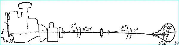
Bring the angles between the driveshaft forks into line with Fig. 3 and 4
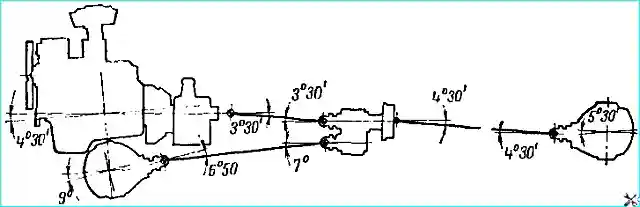
(angle values are given for a fully loaded vehicle in a static state) by replacing worn parts - rubber engine mounts, intermediate support rubber mount (only on GAZ-53A), transfer case rubber mounts
Propeller shaft repair
The propeller shaft from the GAZ-66 vehicle is removed by disconnecting the cardan flanges from the flanges of the gearbox driven shaft and the shaft and the main gear pinion.
On the GAZ-53A vehicle, it is necessary to additionally disconnect the intermediate support bracket from the frame cross member.
Inspection and balancing of parts. The cardan shafts are checked together with the cardans on the cardan transmission removed from the vehicle.
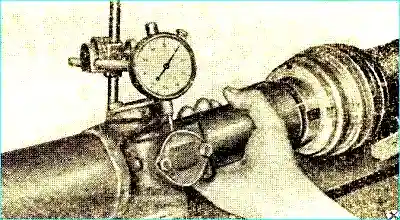
Before disassembling the cardan shaft, measure the total angular play of the cardan shafts, resulting from wear of the splined joint and the tenons of the cardan crosspieces.
When checking the play (Fig. 5), one end of the cardan shaft is secured to the other - a torque moment.
Under the action of a torque of 70 kgf/cm, a play of up to 0.35 mm is allowed (without replacing parts or repairing) measured at a radius of 35 mm for all shafts of the GAZ-66 vehicle and for the intermediate cardan shaft of the GAZ-53A vehicle.
At the same radius, a play of up to 0.17 mm is allowed for the rear cardan shaft of the GAZ-53A vehicle.
A play of 0.25 mm is allowed on the new cardan shafts of the GAZ-66 vehicle and the intermediate cardan shaft of the GAZ-53A vehicle, and a play of up to 0.12 mm is allowed on the new rear cardan shaft of the GAZ-53A or one of the cardans of any shaft.
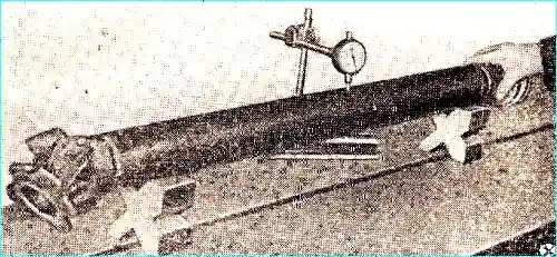
For the new intermediate driveshaft of the GAZ-53A vehicle and all shafts of the GAZ-66 vehicle, the shaft runout at any point along the length of the pipe should be no more than 1 mm.
For the new rear driveshaft of the GAZ-53A vehicle, a runout of no more than 1.2 mm is allowed at any point along the length of the pipe.
Check the runout (Fig. 6) is necessary before balancing the shaft.
Check the amount of radial play in the splined joint of the cardan transmission caused by spline wear.
For a new shaft, the play should not exceed 0.08 mm at a radius of 49 mm.
To determine this value, secure the intermediate cardan shaft in a vice and turn the sliding fork, installing the indicator leg at a radius of 49 mm.
Replacing the cardan transmission
For the GAZ-53A vehicle, the manufacturer carries out careful dynamic balancing of the intermediate and main cardan shafts together (as a set).
Therefore, the cardan transmission on the GAZ-53A vehicle can only be replaced as a whole.
Replacing the cardan shaft
The cardan shaft is replaced in such sequences.
- 1. Clamp the cardan shaft in a vice.
- 2. Unscrew the bolts securing the bearing caps to the cardan fork and remove the bearing caps.
On the cardan shaft of the GAZ-6b, where there are protective caps for the cardans, it is necessary to first unscrew the bolts of the clamping clamps of the protective cap and slide the cap along the pipe.
- 3. Select a mandrel with an outer diameter slightly smaller than the diameter of the cardan bearings.
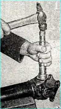
- 4. Install the mandrel at one of the bearings, as shown in Fig. 7.
Using light hammer blows on the mandrel, remove both needle bearings, located on the same axis as the mandrel, from the eyes of the cardan fork. Remove two bearings from the universal joint crosspiece.
- 5. Turn the universal joint crosspiece and the universal joint fork by ¼ turn and push the bearings out of the eyes of the second universal joint fork in the same way.
- 6. Remove the universal joint crosspiece.
When disassembling the universal joint, you should check whether all bearings are lubricated and whether there is dirt in the lubricant, whether the universal joint channels are clogged (a through hole should be visible),
If individual pins are dry and the bearings and seals are not damaged, check whether grease is supplied to all bearings. To do this, wash the crosspiece and wipe the bearings.
Put two bearings on the opposite pins.
Clamp the ends of the bearings in a vice so that the crosspiece rotates easily in the stationary bearings. Put on the two remaining bearings and clamp them with a clamp.
Check the ease of rotation of the pins in the bearings.
Lubricate the oiler with a syringe until the valve is completely open. The valve should open completely at a pressure of at least 1 kg / cm².
If the valve opens at a lower pressure, oil will not flow to all bearings of the new joint.
At a pressure of more than 3.5 kg / cm², grease can flow through the cork seal, thereby compromising its tightness.
To test the valve under pressure, you need to screw it into the tee, into which the pressure gauge is returned and a syringe with grease is connected.
If the valve cannot be repaired, it should be replaced.
Inspect the crosspiece pins.
If there are imprints on them - traces of needles, but the total play of the shaft does not exceed the norm, and there are no vibrations or knocks when driving, the crosspiece can be left.
The depth of the dent should not exceed 0.1 mm.
If the bearings swing on the pin or the pin has worn to a diameter of less than 21.96 mm (nominal 21.986-22.000 mm), then the crosspiece with the bearings as an assembly should be replaced.
It is permissible to replace individual bearings while preserving the crosspiece when only the bearing, bearing cap, oil seal is damaged, or the ring into which the the seal is pressed in
If individual needles are deformed or if at least one of them is lost, the bearing should be replaced.
If the cork seals have shrunk significantly and lost elasticity, they should be replaced. Bearing holes in the forks may be worn to a diameter of 35.05 mm.
Assemble the cardan shaft in the reverse order of disassembly
After assembly, lubricate the cardan shaft through the grease nipple in the crosspiece until grease appears through the check valve.
Replacing the intermediate support bearing and seals of the cardan shaft (only on GAZ-53A)
To replace the bearing and seals of the intermediate support of the propeller shaft, first remove the propeller shaft from the car.
The bearing and seal of the intermediate support are replaced in the following sequence:
- - unscrew the collar of the splined connection seals;
- - disconnect the splined connection;
- - remove the support bracket from the rubber cushion;
- - remove the rubber cushion and four brackets of the bearing caps;
- - clamp the intermediate shaft in a vice;
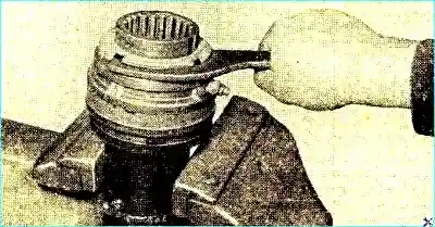
- - bend the locking tabs of the reflector washer from the grooves of the nut;
- - unscrew the nut (Fig. 8) and remove the oil seal reflector washer;
- - remove the bearing assembly with the collars, oil seals and rear spacer sleeve;
- - first remove the rear oil seal collar from the bearing by lightly tapping the mandrel, then the front one;
- - remove the felt oil seals from the bearing oil seal collar seats.
To determine the technical condition after disassembly, wash all the parts of the propeller shaft support, and then, by external inspection, establish: the condition of the bearing (its wear), whether the protrusions of the stamped oil seal collars were in the same plane, and whether the collars were fully pressed onto the outer ring of the bearings.
At the same time, establish whether there is through wear of the oil seal collars from the brackets.
Check if there is tension felt seals on the surface of the bushings on which they operate, or there is a shrinkage of the seal.
To do this, without squeezing the seal out of the cage, place it on the removed bushing.
With a serviceable bearing, having discovered the above deviations in the mutual arrangement of the cages, align the projections of the cages by re-pressing one of them again.
If necessary, the seal cages should be pressed to failure on the outer ring of the bearing.
If there is significant wear on the bearing seal cages, they are replaced with new ones.
Before installing the felt seals in the cages, be sure to soak the seals in warm oil (for engines) for 15 minutes.
The intermediate support and the cardan shaft of the GAZ-53A are assembled in the reverse order disassembly.
In this case, it is necessary to remember and necessarily fulfill the following conditions.
When pressing the seal races onto the bearing, the projections of both races must be located in a line.
When installing the rubber cushion on the bearing, keep in mind that the grease nipple must get into the slot of the cushion.
When mating the splined joint of the cardan shaft, ensure that the position of the ears of the sliding fork with the ears of the welded fork of the front cardan of the intermediate shaft is in the same plane.
A deviation in the position of these forks in one plane of no more than 2º is allowed.
When assembling the shafts, this condition is ensured by aligning the marks on the splined sleeve and the splined fork in one plane.
These marks are knocked out on the parts during manufacture shafts at the factory.
After assembling the intermediate support, lubricate it through a grease nipple. You can add grease to the support during the support assembly process.
Replacing the splined connection oil seals. To replace the splined connection oil seals of the cardan shaft, perform the following operations.
- 1. Unscrew the oil seal cage.
- 2. Disconnect the cardan flange from the flange of the main gear drive pinion shaft.
- 3. Disconnect the splined connection.
- 4. Remove the oil seals from the sliding fork.
Check the condition of the oil seals and the number of located in the splined connection of the grease, determine the suitability of the seals for further work.
Assemble the shaft in the reverse order of disassembly.
Assemble the splined connection according to the marks on the splined sleeve and splined fork.
Tighten the seal collar by hand until the hand force is no longer sufficient.
")

")
")
")
")
")
")
")