Checking and repairing the brake drum. Clean the brake drum from dirt, remove rust and clean out nicks
The brake drum is replaced if it has cracks, if it is deformed or does not fit tightly on the hub.
Before replacing the brake drum, make sure there is no vacuum in the system. Do not press the brake pedal after removing the brake drum.
Small nicks and scratches on the surface of the brake drum can be removed with fine-grained sandpaper, then thoroughly clean the surface of the drum.
If the drum mounted on the hub has an ovality and runout of more than 0.25 mm, as well as deep scratches and nicks, then, based on the outer rings of the hub bearings, bore the drum to the amount necessary to obtain a smooth working surface and a runout of no more than 0.12 mm.
Do not remove a thicker layer from the surface of the drum than necessary.
The diameter of the restored drum should increase by no more than 1.5 mm, i.e. should be no more than 381.75 mm for the brakes of all wheels of the GAZ-66, the rear wheels of the GAZ-53A and 357.25 mm for front wheel brakes of the GAZ-53A vehicle.
If the drum diameter has increased by less than 0.8 mm, then use standard friction linings of the brake shoes, and if by more than 0.8 mm, then use larger friction linings or install metal gaskets between the linings and the rims of the shoes.
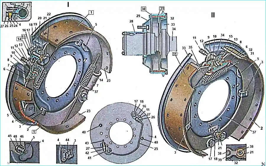
Wheel brake mechanisms: I - Front wheel brake mechanism II - Rear wheel brake mechanism 1, 31 - Brake shoe friction linings. 2 - Friction lining rivet. 3 - Brake shoe guide bracket. 4, 33 - Brake discs (shields). 5 - Adjusting eccentric. 6 - Brake cylinder protective cap. 7 - Brake cylinder (single-acting). 8 - Piston thrust rod. 9 - Brake cylinder piston. 10 - Piston seal. 11 - Rubber cap of the bypass valve. 12 - Bypass valve for bleeding the brake drive. 13 - Piston cuff spacer cup. 14, 35 - Shoe tension spring. 15 - Piston spring. 16, 37 - Brake disc (shield) boosters. 17 - Support pin nut. 18 - Spring washer. 19, 38 - Shoe support pins. 20 - Brake cylinder spring. 21 - Support pin adjusting eccentric. 22 - Support pin washer. 23, 32 - Brake shoes. 24 - Connecting tube nipple. 25 - Brake cylinder connecting tube. 26 - Coupling. 27 - Coupling connecting bolt. 28 - Wheel hub. 29 - Brake drum flange. 30 - Brake drum. 34 - Rear axle housing. 36 - Brake cylinder. 39 - Shoe support pin plate. 40 - Shoe adjusting eccentric bolt. 41 - Shoe support pin installation mark. 42 - Coupling sleeve. 43 - Brake fluid supply pipe to front wheel brake cylinders. 44 - Guide bracket spring. 45 - Adjusting bolt spring washer. 46 - Adjusting eccentric spring
Remove the wheel brake cylinder in the following order.
Bleed the vacuum from the brake booster system.
Remove the wheel and drum. Remove the shoe tension springs.
Disconnect the coupling and the pipeline or hose from the brake cylinder.
When removing the front wheel brake cylinder of the GAZ-66, unscrew the nut with the spring washer of the shoe support pin and remove the pin with the brass eccentric and washer.
Remove the shoe and cylinder from the brake disc.
When removing the rear wheel brake cylinder of the GAZ-66 and the brake cylinders of all wheels of the GAZ-53A, unscrew the mounting bolts of each brake cylinder and remove the spring washers and the screen of the car (GAZ-53A).
Disassemble the wheel brake cylinder in the following order.
Remove the rubber caps from the ends of the brake cylinder, remove the pistons, cuffs, spacer cups with springs. Remove the rubber caps from the pistons.
Unscrew the bypass valve from the cylinder.
Wash the brake cylinder parts in pure alcohol.
Checking and repairing the wheel brake cylinder parts. Wash the wheel brake cylinder in alcohol, and wipe the mirror with a clean napkin.
If there is corrosion, scratches, scuffs, it is honed to a value of no more than 0.125 mm, i.e. no more than Ø 35.152 mm.
In this case, you need to install new cuffs.
If after honing the defect is not eliminated or there is a fluid leak from the assembled cylinder, then bore the cylinder and then hone under one of the repair sizes.
In this case, pistons, cuffs and spacer cups of the corresponding repair size are installed.
The piston of the wheel brake cylinder must not have corrosion and scoring. If they are present, the piston should be replaced.
If there is a swing of the thrust rod, then also replace the piston.
The cylinder cuff must be elastic, with a sharp working edge and without defects.
The protective cover must not have cracks and must be elastic.
The spring must not have corrosion. Under a load of 0.95+ 0.1 kgf, the spring should be compressed to a height of 25 mm.
The expansion cup of the cuff should not have dents or nicks, when installed in the cylinder, it should fit evenly against the sealing edge of the cuff and not touch its bottom.
The bypass valve should have a good sealing cone surface. The longitudinal and transverse holes should be clean.
Assembly and testing of the wheel cylinder
Before assembly, wash all parts of the wheel cylinders in pure alcohol and blow them with compressed air. Lubricate the cuffs and the cylinder mirror with brake fluid.
Assemble the cylinder in the reverse order of disassembly. To test, immerse the cylinder in alcohol and supply air under a pressure of 5-6 kg/cm² into the threaded hole.
With the bypass valve unscrewed, air should vigorously escape from the hole. With the valve screwed in, there should be no air escape.
Put the rubber cap on the bypass valve.
Installing the wheel brake cylinders
The wheel brake cylinders are installed in the reverse order of their removal.
When installing the coupling with new copper gaskets, do not tighten the bolt all the way.
Finally tighten the bolt after connecting the pipeline to the coupling. After installing all the parts in place, adjust the brakes and bleed the system.
Brake pads
When replacing the brake pads, do not press the brake pedal, as the brake fluid may leak out. Brake pads must be removed in the following sequence.
First loosen the wheel mounting nuts. Hang the wheel so that it rotates freely. Remove the wheel and drum.
Secure the wheel cylinder pistons from falling out. Remove the brake pad tension spring(s).
Unscrew the brake pad support pin nuts. While holding the support pins from turning with wrenches, remove the pins, eccentrics, washers, and the support pin plate.
Checking and repairing the pads
If the linings are coated with gum, clean their surface with sandpaper; if they are oily, wash them with gasoline.
If uneven braking is noticed during operation, it is necessary to check the curvature of the linings using a template with a radius of 189.80 mm and the front lining (GAZ-53A brakes with a radius of) 177.55 mm.
A clearance of no more than 0.30 mm is allowed.
Deviation from the circle and uneven wear can be corrected by grinding if the rivets are sunk to a sufficient depth.
If the rivets are sunk less than 0.5 mm deep, the linings replace.
Do not replace only one of the brake pads or linings on one side of the car.
If it is necessary to replace the linings on one brake, replace them on the other side at the same time to avoid skidding the car when braking.
When replacing the linings, it is necessary to:
- - drill out or cut off the lining rivets;
- - clean up all burrs and irregularities of the pad;
- - check whether the pad is deformed, whether the rim fastening to the rib has weakened;
- - check the condition of the hole for the support pin;
- - check the curvature of the rim of the pad with a template. With a template radius of 182 mm for all pads and 172 mm for the front brake pads of the GAZ-53A, a 0.3 mm thick feeler gauge should not pass between the template and the pad rim;
- - install a new friction lining on the pad and, starting from the middle holes, rivet it to the rim with new rivets;
- - check the gap between the lining and the pad rim.
The lining should fit tightly against the rim. A 0.25 mm feeler gauge should not pass between them to a depth of more than 20 mm.
The lining should not protrude beyond the pad rim in width. The ends of the pads should have bevels 8-14 mm long;
- - grind the pads so that their diameter is 0.2-0.4 mm less than the drum diameter. This will speed up the adjustment of the gaps, ensuring uniform adhesion of the pads to the drum;
- - install the pads in the reverse order of their removal, adjust the brakes and bleed the brake system. When installing the pads, make sure that the support pins are installed with the marks inward.
For brake adjustment, see the article - Design, malfunctions and maintenance of the GAZ-66, GAZ-53 brakes
After running in the brakes, repeat the adjustment of the gap between the pads and the brake drums.