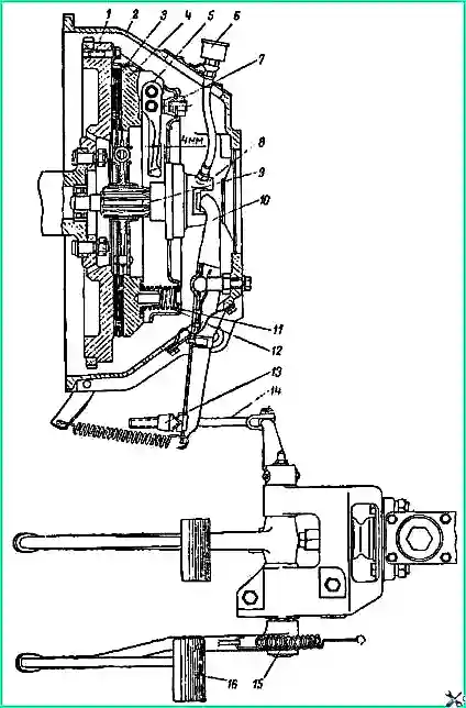
The car’s clutch is dry, single-plate, with a damper device, installed in a cast aluminum housing (Fig. 1)
The clutch of the GAZ-66 car differs from the clutch of the GAZ-53A car only in the different thrust pins of the clutch release forks (which is due to different clutch release drives), the ignition installation hatch covers and the presence of an ignition installation pin pressed into the clutch housing of the GA3-66 car ( There is no pin in the GAZ-53A clutch housing).
The pressure and driven disks, as well as the clutch release clutches of the GAZ-53A and GAZ-66 vehicles are no different.
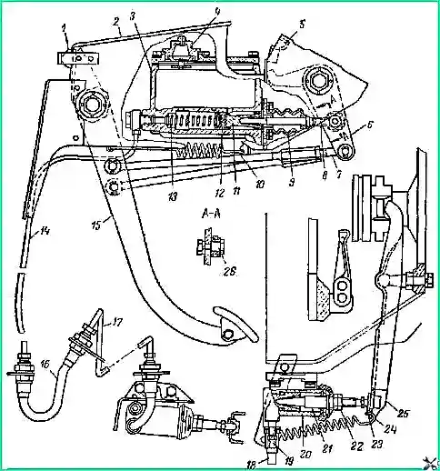
Clutch release drive of the GAZ-66 car: 1 - rubber buffer; 2 - front bracket; 3 - main cylinder; 4 - plug; 5 - rear bracket; 6 - intermediate lever; 7 - traction; 8 - pusher; 9 - protective cover; 10 in 24 - tension springs; 11 - piston of the main cylinder; 12- cuff; 13 - return spring; 14 and 17 - pipelines; 15 - pedal; 16 and 18 - flexible hoses; 19 - bypass valve; 20 - working cylinder; 21 - pusher; 22 - lock nut; 23 - pusher tip; 25 - clutch release fork; 26 - eccentric bolt
The clutch release drive of the GAZ-53A car is mechanical (see Fig. 1), the clutch release drive of the GAZ-66 car (disengagement 2) is hydraulic.
Clutch maintenance
When lubricating the clutch release clutch thrust bearing, it is necessary to squeeze out the lubricant in the amount of one full fill of the grease cap.
More frequent and generous lubrication may result in excess lubricant reaching the clutch discs, which may cause failure.
More infrequent lubrication of the bearing leads to thickening of the lubricant in the holes supplying it from the annular cavity of the coupling to the bearing, and to subsequent failure of the bearing due to the cessation of lubricant supply.
Particular attention should be paid to the care of the clutch release drive of the GAZ-66 car in connection with the use of GTZh-22 fluid as a working fluid, since it has strong oxidizing properties.
For normal operation of the clutch of a GAZ-53A vehicle, it is necessary to ensure a gap of 4 mm between the heads of the clutch release levers and the thrust bearing.
To obtain this clearance, it is necessary to periodically check and adjust the free play of the clutch pedal, which should be 35-45 mm.
The free play of the clutch pedal is adjusted by changing the length of the rod connecting the clutch release fork to the lever on the pedal shaft.
An increase in free play is achieved by unscrewing the nut on the rod, a decrease - by tightening it.
For normal operation of the clutch of a GAZ-66 car, it is necessary to ensure a gap between the heads of the release levers and the thrust bearing of 2 mm and a gap between the pusher and the piston of the master cylinder of 0.5-1.5 mm.
When adjusting the clutch release drive, first adjust the gap between the pusher and the master cylinder piston using eccentric bolt 26 (see Fig. 2).
The normal clearance corresponds to a pedal free play of 3.5 - 10 mm.
After adjustment, the nut of bolt 26 is tightened.
If it is not possible to ensure the required free play of the pedal using an eccentric bolt, then it must first be adjusted by changing the length of rod 7.
The gap between the clutch release thrust bearing and the lever heads is adjusted by changing the length of the working cylinder pusher, in this case it is necessary to obtain a free play of the end of the clutch release fork of 3.5 mm.
After adjustment, the total pedal travel should be 30-37 mm.
For normal clutch operation, it is also necessary to ensure that the piston stroke of the working cylinder is at least 23 mm.
With a smaller stroke, the clutch may not disengage completely. The piston stroke of the working cylinder is not regulated.
A reduced stroke indicates air leaks in the hydraulic drive system. In this case, it is necessary to pump the fluid in the hydraulic drive.
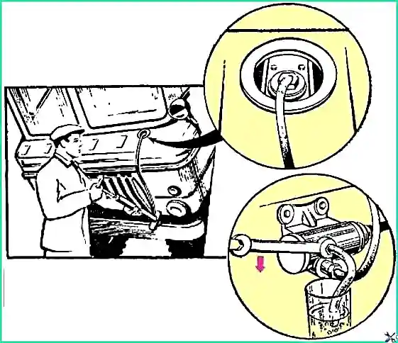
To do this, remove the rubber protective cap from the head of the bypass valve of the working cylinder and place a bleeding hose on the head.
Place the end of the hose into a glass container into which a little liquid is poured, and unscrew the valves ¾ of a turn.
Screw the tire pump hose to the threaded end of the master cylinder plug and use the pump to create a slight pressure in the system (Fig. 3).
At the same time, under the influence of pressure, liquid from the master cylinder reservoir fills the hydraulic drive system, displacing air through the bypass valve of the working cylinder.
The air from the hose will pass through the liquid in the glass container in the form of bubbles.
After the air exit from the hydraulic drive system stops (bubbles stop coming out of the bleeding hose), close the valve and remove the bleeding hose.
Place a protective cap on the head of the bypass valve and, unscrewing the master cylinder plug, add fluid to a level of 15-20 mm below the upper edge of the filler hole; screw the plug.
When pumping, do not allow the bottom of the master cylinder to be exposed.
Therefore, if about a glass of liquid has leaked out of the system, stop pumping and continue it only after adding liquid to the main cylinder.
Clutch malfunctions and ways to eliminate them
- Causes of malfunction
Remedy
Clutch engagement is not smooth:
- Oiling the friction linings of the driven disk
Replace the driven disk or install new friction linings.
If the oiling is slight, you can sand the linings with fine sandpaper, after washing them with gasoline
- Non-simultaneous pressing of the thrust bearing on the heads of the clutch release levers
Adjust the relative position of the lever heads using nuts 7 (see Fig. 1) of the support forks
- Excessive wear of friction linings (up to rivets)
Replace the disc or change the linings
Incomplete disengagement of the clutch - “the clutch will close” (difficulty shifting gears and gear noise in the gearbox when shifting):
- Availability of air in the hydraulic drive system
Bleed fluid in the system
- Large free play of the clutch pedal
Adjust the free play of the clutch pedal
- deformation of the driven disk
Replace the disk or edit it
- Non-simultaneous pressing of the bearing on the heads of the clutch release levers
Adjust the relative position of the levers
- Wear of the inner cuff of the master cylinder
Replace the cuff
Incomplete engagement - “clutch slips”:
- No gap between the heads of the clutch release levers and the end of the thrust bearing
Adjust the free play of the clutch pedal
- Loosening clutch pressure springs
Replace springs
- Disc oiling
Replace discs or friction linings
- Excessive wear of the friction linings, flywheel friction surface or pressure plate
Replace the driven discs or disc linings, and repair the flywheel and pressure plate by grinding the friction surfaces
Noise, squeaking when pressing the clutch pedal:
- Lack of lubrication in the clutch release bearing
Lubricate the bearing
- Clutch bearing wear
Replace the bearing
Clutch repair
The main clutch parts that require replacement or repair during operation are the driven and pressure plates, as well as the clutch release bearing.
Replacing the clutch release bearing
To remove the clutch release bearing, remove the gearbox together with the clutch, disconnect the clutch release spring, remove the clutch and press the bearing off it.
Before pressing a new bearing onto the coupling, check that it is filled with lubricant.
When installing a gearbox with a clutch on a car, you need to make sure that the lubricant supply hose to the bearing is not damaged; to do this, thread it inside the clutch housing before finally installing the gearbox on the clutch housing studs.
If the grease supply hose to the bearing was removed or replaced for any reason, fill it with grease when installing.
To do this, squeeze the contents of a fully filled oil can into it twice; That Only the third time will the oiler supply lubricant to the clutch release bearing.
Removing the clutch discs
To remove the clutch discs from the vehicle, remove the gearbox.
Having removed the lower part of the clutch housing, unscrew the bolts securing the clutch housing to the flywheel through the lower housing hatch.
In this case, you should unscrew all the bolts gradually so as not to bend the casing support legs or tear off the bolts that are unscrewed last.
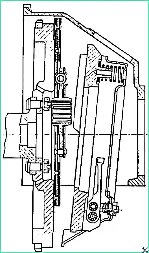
Clutch discs separated from the flywheel are removed from the crankcase in a certain position.
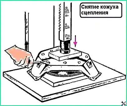
First, remove the pressure disk by turning it down with one of the casing legs and lifting the driven disk (Fig. 4), then the driven one.
Disassembly and assembly of the clutch pressure plate
The pressure plate is disassembled in the following order:
- - make marks on the casing and pressure plate in order to maintain the original position of these parts during assembly and, therefore, maintain balancing;
- - place the disk on the press table, placing a wooden stand under the disk so that the casing legs can move down;
- - a wooden block is placed on top of the casing so that it does not cover any of the adjusting nuts of the clutch release lever support forks (Fig. 5);
- - pressing the block with a press, compress the clutch springs to relieve the clutch release levers from the effort, unscrew the nuts of the lever support forks, slowly release the press, remove the clutch cover, support fork springs and pressure springs;
- - carefully remove the fingers located in the protrusions of the pressure plate, separate the levers with support forks from the pressure plate and assemble the needle bearing rollers;
- - carefully remove the fingers of the lever support forks, separate the support forks and assemble the needle bearing rollers.
If warping, scoring, annular grooves or cracks caused by overheating are found on the friction surface of the pressure disk, the disk is replaced or repaired by grooving and grinding; the thickness of the repaired disk should be no more than 1.5 mm less than the thickness of the new disk.
The difference in size from each of the axes of the three holes under the axes of the clutch release levers to the machined surface should be no more than 0.15 mm, and the surface itself should be flat (when checking on a plate, the 0.05 mm probe should not pass through).
Broken or lost pressure springs must be replaced (it is advisable to replace all springs).
The force of the pressure spring should be 62.5-68 kg when compressed from a free length of 61 mm to a length of 40 mm.
The springs of the support forks of the clutch release levers that have lost their elasticity also need to be replaced, since otherwise, at high engine speeds, the heads of the release levers may move back, and this will cause continuous operation of the thrust bearing and its premature wear.
When compressing the support fork spring from a free length of 12.5 mm to a length of 9.5 mm, the spring force should be 14 ± 1.5 kg.
The pressure plate with casing and levers are assembled in the following order:
- - assemble the clutch release levers with the support forks; To do this, rubber balls with a diameter of 8.5 mm are placed in the corresponding holes of the levers, after which the gaps between the balls and the walls of the holes are filled with rollers of needle bearings (each bearing must have 19 rollers). Rubber balls are necessary to ensure that the rollers do not fall apart during assembly.
- - After installing the rollers, one or two drops of oil used to lubricate the gearbox are introduced into the holes of the levers;
- - insert the clutch release levers with the rollers into the slots of the support forks, then carefully insert the fingers and pin them. When assembled, the rubber balls are pushed outward with your fingers;
- - the pressure plate with clutch release levers is assembled in the same way;
- - using, as during disassembly, a press, a wooden lining and a block, assemble a pressure disk with a casing, springs and heat-insulating washers. In this case, the marks made during disassembly on the disk and casing are aligned.
When assembling a casing with a repaired disk, metal washers are placed under the pressure springs, in addition to the heat-insulating washers, to compensate for the reduction in the thickness of the disk and thus maintain the force of the pressure springs (instead of placing washers under the springs, you can make a ring groove for the flywheel under the feet of the pressure disk, the depth of the groove should be equal to the amount by which the thickness of the pressure plate was reduced after repair).
After assembly, adjust the position of the clutch release lever heads.
If there is no device, this operation can be carried out using a free flywheel.
To do this, the pressure plate assembled with the casing is placed on the friction surface of the flywheel.
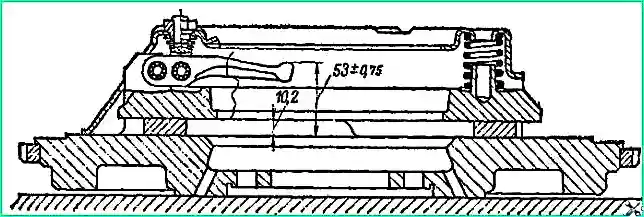
Between the pressure plate and the flywheel, place washers 10.2 mm thick in three places and tighten the bolts securing the casing to the flywheel.
Using the adjusting nuts of the pull-out levers, ensure that the size from the surface of the flywheel to the ends of the levers is 53 ± 0.75 mm (Fig. 6), and the deviation of the ends of the levers from one plane is no more than 0.3 mm;
- after this the adjusting nuts are unscrewed. Instead of washers, you can use a new driven disk when making adjustments.
Clutch driven disc repair
If there is significant wear (almost to the rivets) or damage to the friction linings of the driven disk, the linings are replaced.
Both linings must be replaced at the same time, since the difference in the thickness of the linings will disrupt the normal operation of the clutch.
To remove worn or damaged linings, you should drill out and carefully knock out the rivets securing the linings to the leaf springs and disk with a punch.
Rivet new linings so that the depth of the rivets is at least 1.5 mm.
The runout of a disk with new linings should be no more than 0.7 mm when measured at a radius of 125 mm from the center of the disk.
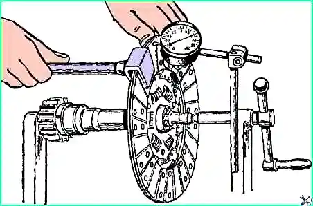
If the disc runout is greater than the permissible value, then when disengaged the clutch will “drive” (incomplete disengagement of the clutch).
If necessary, the driven disk is adjusted using the mandrel shown in Fig. 7.
Installing clutch discs. Repaired clutch discs are installed on a car in the following order:
- - refractory lubricant (constalin or grease 1-13) is placed in the hole of the ball bearing of the gearbox drive shaft installed in the flywheel;
- - wipe the friction surfaces of the flywheel and pressure plate with a piece of clean cloth lightly moistened with gasoline;
- - insert the driven disk into the crankcase, first, making sure that the short part of its hub is facing the flywheel, then insert the pressure plate, turning one of its support legs down and pressing it against the flywheel;
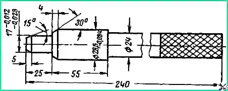
- - center the driven disk relative to the axis of the engine crankshaft. To do this, insert the mandrel shown in Fig. into the splined hole of the disc hub through the rear hole of the clutch housing. 8, so that its end fits into the ball bearing in the flywheel.
- To center the driven disk, you can use the free drive shaft of the gearbox;
- - before attaching the clutch casing to the flywheel, align the marks on the flywheel and casing, which are knocked out at the factory after the crankshaft, flywheel and clutch are balanced together;
- - gradually tighten all the bolts securing the casing to the flywheel;
- - install the gearbox and the lower part of the clutch housing.
Repair of the clutch release drive of the GAZ-66 car
After disassembling the main and working cylinders, inspect their parts, as well as the parts of the pedal bracket.
Nominal dimensions and maximum dimensions up to which wear of parts is allowed without repair are indicated in table. 5.
Table 5. Nominal and maximum permissible dimensions of clutch release drive parts without repair
Diameter of the master cylinder bore for the piston:
- - nominal size - 22 +0.023 mm;
- - permissible size - 22.085 mm
Outer diameter of master cylinder piston:
- - nominal size - 22 -0.040 mm;
- - permissible size - 21.810 mm
Bore diameter of working cylinder for piston
- - nominal size - 24 +0.023 mm;
- - permissible size - 24.085 mm
Working cylinder piston outer diameter
- - nominal size - 24 -0.020 mm;
- - permissible size - 23.840 mm
Inner diameter of clutch pedal bushing
- - nominal size - 18 +0.105 mm;
- - permissible size - 18,250 mm
Inner diameter of the pusher axis bushing
- - nominal size - 14 +0.070 mm;
- - permissible size - 14.210 mm
If scratches or scratches are detected on the mirror of the master or slave cylinders, It is possible to replace the cylinder or grind and hone it to one of the repair sizes recommended in the table. 6 and 7.
Table 6. Repair dimensions of parts of the clutch release master cylinder
Nominal size:
- - cylinder diameter - 22 +0.023 mm;
- - piston diameter - 22 -0.040 mm;
- - diameter of the working edge of the inner cuff - 23±0.2 mm
First repair size:
- - cylinder diameter - 22.25 +0.023 mm;
- - piston diameter - 22.25 -0.040 mm;
- - diameter of the working edge of the inner cuff - 23.5±0.2 mm
Second repair size:
- - cylinder diameter - 22.50 +0.023 mm;
- - piston diameter - 22.50 -0.040 mm;
- - diameter of the working edge of the inner cuff - 23.5±0.2 mm
During assembly, it is allowed to install internal sealing collars of the nominal size into the main cylinder of the first repair size.
Outer sealing collars of nominal size can be installed for the first and second repair sizes.
It is allowed to install a sealing collar of a nominal size into the working cylinder of the first repair size.
Table 7. Repair dimensions of the clutch release working cylinder parts
Issue before June 1967:
- - nominal: cylinder diameter - 24 +0.023 mm, piston diameter - 24 -0.02 mm, cuff working edge - 25 +0.20 mm;
- - first repair: cylinder diameter - 24.25 +0.023 mm, piston diameter - 24.25 -0.02 mm, cuff working edge - 25.5 +0.20 mm;
- - second repair: cylinder diameter - 24.5 +0.023 mm, piston diameter - 24.5 -0.02 mm, cuff working edge - 25.5 +0.20 mm
Issue since June 1967:
- - nominal: cylinder diameter - 22 +0.023 mm, piston diameter - 22 -0.02 mm, cuff working edge - 22.7 +0.20 mm;
- - first repair: cylinder diameter - 22.25 +0.023 mm, piston diameter - 22.25 -0.02 mm, cuff working edge - 23.2 +0.20 mm;
- - second repair: cylinder diameter - 22.5 +0.023 mm, piston diameter - 22.5 -0.04 mm, cuff working edge - 23.2 +0.20 mm
The spherical tips of the pushers of the main and working cylinders, as well as the spherical recesses in the cylinder pistons and in the thrust pin of the clutch fork must be smooth, without marks.
The tips of the pushers must mate with the recesses of the pistons along the spot in the center of the spheres. If contact occurs along the ring, then the mating is incorrect and can cause sticking of the pusher, misalignment and wear of the piston.
When sanding the sphere on the pushers, you need to ensure that the contact is not on the ring, but on the spot.
Inspect the ends of all plastic bushings and washers of the pedal bracket, carefully clean off the burrs on their ends.
Check that the tension and return springs are not loose.
If the springs are weakened, replace them.
")

")
")
")
")
")
")
")