The hydraulic brake booster should be removed in this order.
Remove vacuum from the amplifier system.
Disconnect the two hydraulic tubes, rubber hoses of the vacuum and air pipelines from the amplifier.
Drain the brake fluid from the booster into a container.
Remove the amplifier assembly with brackets.
Remove the couplings with bolts and copper pipe gaskets.
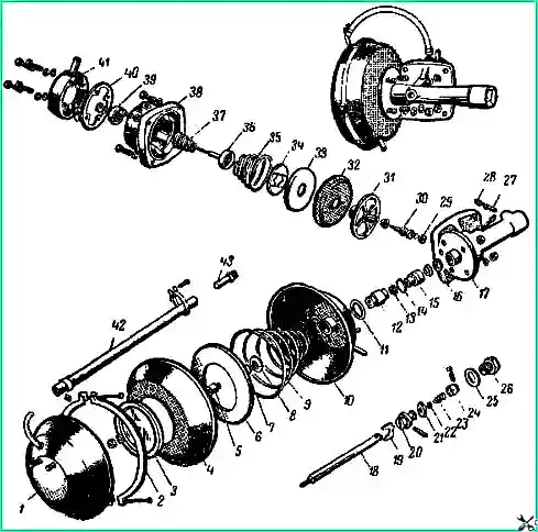
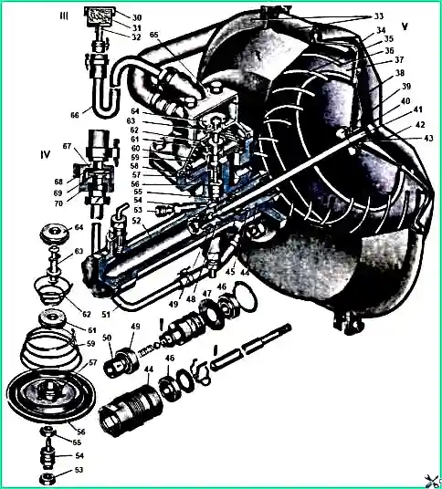
Disassembling the hydraulic vacuum booster
The hydraulic vacuum booster (Fig. 1) must be disassembled in the following sequence.
Clean the outer surface of the amplifier from dirt.
Install the amplifier in a vice. Install copper spacers between the vise jaws.
Disconnect the rubber hose from the rear half of the amplifier chamber housing, and then unscrew it together with the fitting from the control valve housing.
Make marks on the amplifier chamber housings to ensure their subsequent correct assembly.
Make marks on the hydraulic cylinder and the camera body adjacent to it.
Remove the two clamps from the amplifier housing.
Holding diaphragm 4 with your hand (see Fig. 1), unscrew the pusher nut.
Remove sequentially the spring nut washer, small diaphragm plate 3, diaphragm, spacer sleeve 5, large diaphragm plate 6, spring 9.
Carefully remove the rubber ring along with the pusher washer.
Remove the front half of the housing, the cardboard spacer and the rubber sealing ring.
Unscrew the end cap 26 and remove the copper gasket 25.
Unscrew nut 12 of the cylinder seal housing. Remove collar 13 from the seal housing nut.
Remove piston 20 with pusher 18 from the cylinder.
Unsplit the piston, remove the cuff cap 24, remove spring 23 from the piston, ball valve 22, remove the cuff from the piston.
Press the pin out of the piston, remove the piston pusher and plate pusher 19 of the ball valve.
Using light pressure, remove the piston thrust washer 16 and the seal housing 15 with the rubber ring 14 and the cuff 13 from the cylinder.
Remove the rubber ring from the seal housing and remove the cuff.
Unscrew the bypass valves 27 from the amplifier cylinder.
Remove the cover 41 of the housing 38 of the control valve 31 with gasket 40
Remove the control valve body and remove the control valve from the cylinder.
Remove the spring from the valve body. Remove the valves and their spring.
Using a screwdriver, remove flat washer 34 from the control valve, diaphragm washer 33 and diaphragm 32.
Remove the sealing collar 29 from the lower end of the control valve piston 30.
If the sealing lip of the upper end of the valve piston is in poor condition, press it out.
Remove the piston seal.
Checking and repairing the hydraulic vacuum booster
Rinse all metal parts in kerosene, with the exception of rubber parts and parts of the amplifier cylinder. Wash these parts in pure alcohol or brake fluid.
Do not allow oil to come into contact with rubber parts. Replace any worn or damaged parts.
The working surfaces of the hydraulic vacuum booster cylinder must be free of scratches, burrs and corrosion.
If these deficiencies are found, it should be honed to a diameter of no more than 22.125 mm for the working surface of the amplifier piston and no more than 12.58 mm for the working surface of the control valve piston.
In this case, new cuffs should be installed.
If after honing the defect on the cylinder mirror has not been eliminated, then the cylinder should be bored and honed to one of the repair dimensions. In this case, pistons and cuffs of repair size must be installed.
Check the threads in the cylinder holes and the cleanliness of the edges for the bleeder valves.
There should be no broken threads, and the edges in the bypass holes should be clear and even around the entire circumference.
The cylinder pistonof the hydraulic vacuum amplifier must be free of corrosion and scoring. If there is wear on one side, scoring, corrosion or a loose fit of the ball (valve), replace the piston.
The piston pusher must have a smooth surface without scoring or rust. If these defects are found, replace the pusher.
The diaphragm of the amplifier chamber and control valve if a rupture, crack, compression of the sealing ring edges or other damage is detected, replace it.
The spring of the amplifier chamber should be compressed to a height of 120 mm under a load of 9-12 kg.
The cuffs of the cylinder piston and the control valve piston must be elastic, with sharp sealing edges.
Rubber sealing rings must not have deformation, cracks, or ruptures.
The piston valve (ball) with a diameter of 6.35 ± 0.025 mm should not have any edges or deposits on the surface and should sit tightly in the amplifier piston seat.
The control valve piston must be free of scoring and corrosion and must be securely held in the control valve. If these defects are found, replace the piston.
The control valve must ensure reliable pressing of the piston into it and reliable retention of the diaphragm spring washer.
If this is absent or there are nicks on the surface of the seat, replace the valve.
The control valve spring must be compressed with a force of 2.5 ± 0.5 kg to a height of 17 mm.
The control valve body must have a smooth annular groove for reliable sealing of the valve diaphragm and a seat for the air valve without nicks.
Atmospheric valves and vacuum valves must have a smooth rubber surface without scratches or roughness for a tight fit of the valves to the seats.
The atmospheric valve spring under a load of 0.3 - 0.05 kg should be compressed to a height of 20 mm.
The spring washer of the control valve diaphragm must be flat, with sharp edges along the perimeter of the ledges of the internal diameter; a non-flatness of the washer of 0.2 mm is allowed under a load of 1 kg.
Assembling a hydraulic vacuum booster
Before assembling, wash the parts. Immerse the cuffs in brake fluid at a temperature of at least + 15°C.
Lubricate the internal cavity of the cylinder with castor oil or brake fluid.
Assemble the hydraulic vacuum booster in the reverse order of disassembly.
When assembling, do not push the piston into the amplifier cylinder more than 100 mm from the edge of the cylinder, so as not to damage the piston collar.
When assembling the front camera housing with the cylinder, ensure that the holes in the housing, gasket and cylinder are aligned.
Do not put washers under the nuts, the bolts of which are used to fasten the amplifier.
The control valve assembly is shown in Fig. 2 and 3.
Installation and testing of a hydraulic vacuum booster
Install the amplifier in the reverse order of its removal.
The couplings are attached with new copper gaskets.
After installing the amplifier, bleed the brake system.
After assembling and installing the amplifier on the car, check (test) its operation. Tests should determine:
- tightness of the booster cylinder, reliability of the piston pusher seals, control valve seals and reliability of all threaded connections of the hydraulic vacuum booster cylinder.
To do this, press the brake pedal with maximum force, in the absence of vacuum in the system and hold the pedal for 2-3 minutes, make sure that there is no fluid leakage from the system.
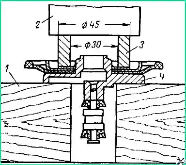
After assembly, the hydraulic vacuum amplifier cylinder (before assembling it with the camera body) must be checked for leaks under a pressure of 90 kg/cm 2.
Brake fluid must be supplied to hole 1 (Fig. 4). In this case, there should be no leakage of liquid from any point of the cylinder within 1.5 minutes.
Check: whether there is a decrease in the fluid level in the reservoir of the main brake cylinder;
- tightness of the cuff and valve (ball) of the piston of the amplifier cylinder.
To determine the tightness of the cuff and piston valve, you need to press the brake pedal with a force of 30 - 40 kg in the absence of vacuum in the system.
Then start the engine, with the pedal moving slightly closer to the cabin floor.
Hold the pedal with the same force (30-40 kg) for 2-3 minutes and without stopping the engine, make sure that it does not move;
- - disinhibitability of the entire braking system. To do this, lift one of the front wheels of the car or the rear axle and, with the engine running, press the pedal and then release it. The wheel should rotate freely;
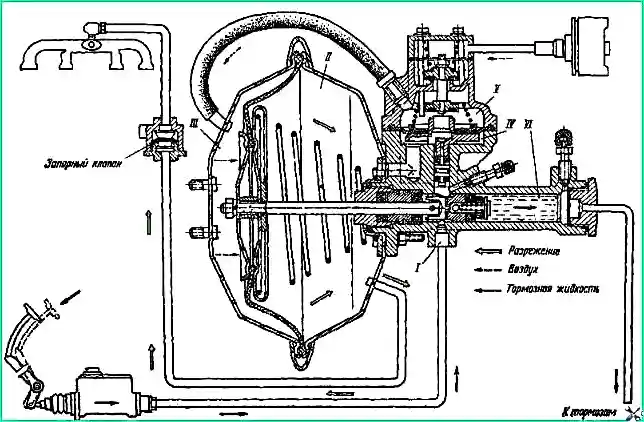
- - tightness of the vacuum chamber, the amplifier control valve and the entire vacuum piping system. To do this, start the engine and, after letting it run for a while, turn it off.
After 2-3 minutes, press the brake pedal.
If the vacuum line, shut-off valve, amplifier chamber and control valve are sealed, you should hear the hiss of air entering the amplifier through the air filter, which is located in the driver's cabin.