The regulation system allows you to change the air pressure in the tires from the driver's seat both when the car is parked and when the car is moving, to control the tire pressure, and to continue driving the car with minor damage to the tire.
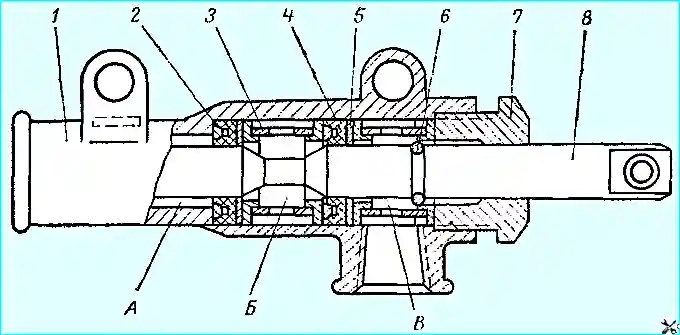
The composition of the tire pressure regulation system (Fig. 1):
- - Compressor 1.
- - Air cylinder 4.
- - Control valve 7.
- - Pressure regulator 3.
- - Safety valve 5.
- - Wheel air shut-off valves.
- - Seal blocks installed in the axle journals (Fig. 2).
- - Pressure gauge.
- - Pipes and hoses.
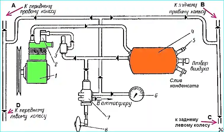
Tire pressure regulation system diagram:
- Compressor.
- Unloading cylinder.
- Pressure regulator.
- Air tank.
- Relief valve.
- Manometer.
- Control valve.
- Control valve handle.
- - (A) To the front right wheel.
- - (B) To the rear right wheel.
- - (C) To the front left wheel.
- - (D) To the rear left wheel.
Features of the compressor:
The compressor of cars with a tire pressure regulation system, unlike the compressor of cars without this system, has a relief cylinder screwed into the threaded hole of the compressor head above the inlet valve.
The principle of operation of the system:
- - When the pressure in the system increases to 5–5.5 kg/cm², the pressure regulator connects the relief cylinder to the air tank. As a result, air under pressure enters the unloading cylinder and moves piston 6 (see Fig. 3) downwards.
- - The piston rod, having moved downwards, opens valve 12 and connects the cylinder cavity with the engine air filter. When the compressor piston moves upwards (compression stroke), air is forced back into the air filter, and not into the system, i.e. the compressor operates without load.
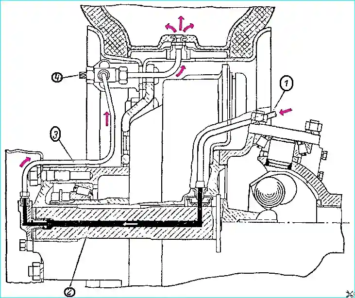
Scheme of air supply to the wheel tire:
- Air supply hose to the seal block.
- Air duct.
- Air supply pipe to the wheel valve.
- Air valve.
Pressure regulator:
- - When When the pressure in the system drops to 4–4.5 kg/cm², the pressure regulator connects the unloading cylinder to the atmosphere. Piston 6 with the rod rises upward under the action of spring 7, the inlet valve is released, and the compressor again begins to pump air into the system.
- - The pressure regulator (Fig. 4), together with the unloading cylinder, automatically maintains the pressure in the system within the range from 4–4.5 to 5–5.5 kg/cm².
Compressor head:
- Head housing.
- Unloading housing cylinder.
- Coupling.
- Nipple.
- Cuff.
- Piston.
7, 9, 13. Springs.
- Plug.
- Discharge valve.
11, 16. Seats.
- Inlet valve.
- Inlet valve body.
Relief valve (Fig. 5):
Installed in case of failure of the pressure regulator. Adjusted to a pressure of 6 kg/cm², which is higher than that of the pressure regulator.
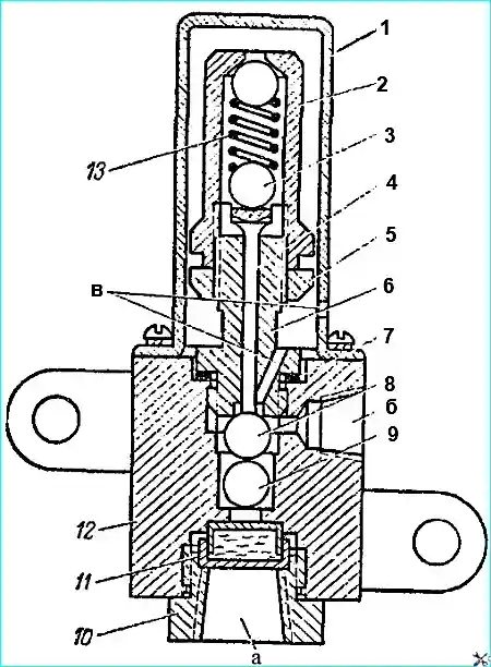
Control valve (Fig. 6):
Allows you to connect the wheel tubes to the compressor (when inflating the tires with air), to the atmosphere (when the tire pressure drops), or lock them (to maintain the existing tire pressure).
Air cylinder:
Designed to settle the condensate of water vapor and oil that enter the system from the compressor along with compressed air.
Tire pressure regulation system malfunctions and how to eliminate them:
- Air leak with the control valve in neutral position and the wheel shut-off valves open:
- Loose connections in pipelines and hoses.
Solution: Tighten the connections or replace the air duct elements.
- The sealing cuffs of the oil seal block are damaged.
Solution: Replace the oil seal block or damaged cuffs.
- When inflating the tires with air, the pressure in them does not rise to 2.8 kg/cm²:
- Large air leak in the system.
Solution: Determine the leak locations and eliminate them.
- The piston of the unloading cylinder is jammed due to contamination or a bent rod.
Solution: Replace the bent rod with the piston. Disassemble, wash and lubricate the cylinder parts.
- The pressure regulator does not connect the unloading cylinder to the atmosphere when the pressure in the system drops:
- Solution: Disassemble the regulator, wash the parts in gasoline, dry and reassemble. Adjust if necessary.
- Worn piston rings or compressor cylinder:
- Solution: Repair or replace the compressor.
- Frequent operation of the safety valve:
- Malfunction of the pressure regulator or safety valve.
Troubleshooting: Disassemble, wash and assemble. Adjust if necessary.
- In winter, one or all tires do not inflate or deflate:
- Frozen condensate clogs the air duct.
Troubleshooting: Find the blockage, warm it up and blow it out with air.
Repairing the tire pressure regulation system:
- Disassembling, inspecting and assembling the system components:
- - Before removing the system components, release the compressed air from the air cylinder.
- - Disassemble the pressure regulator in the following order:
- - Remove the casing 1 of the regulator.
- - Loosen the lock nut 5, unscrew the adjusting cap 2 and remove the valve stem 4, spring 13 and support balls 3.
- - Unscrew the seat 6 of the regulator, remove the adjusting linings 7 and ball valves 8 and 9.
- - Unscrew the cover 10 of the filter and remove the filter 11.
- - If damage is found, the part or regulator must be replaced.
- - Before assembly, wash all parts in gasoline.
- - Assemble the regulator in the reverse order.
- - Check the operation regulator: it should switch off the compressor at a pressure of 5–5.5 kg/cm² and switch it on at a pressure of 4–4.5 kg/cm².
- Adjusting the pressure regulator:
- - By rotating the cap 2, achieve switching on the compressor at a pressure of 4–4.5 kg/cm².
- - By changing the number of adjusting shims 7, achieve a pressure of 5–5.5 kg/cm², at which the compressor switches off.
- Safety valve:
- - To disassemble, unscrew the seat 1, remove the ball 3 of the valve and the guide rod 5 with the spring 6.
- - If the ball valve or its seat is damaged, replace details.
- - Before assembly, wash the parts in gasoline.
- - After assembly, adjust the valve to a pressure of 6 kg / cm².
- Control valve:
- - To disassemble, unscrew the lock screw of nut 7, remove the valve 8, seals 4, spacer rings 2, bushings 3 and support washers 5.
- - Replace damaged seals.
- - Before assembly, wash and lubricate the parts.
- - Adjust the tension of the seals with nut 7.
- Seal blocks:
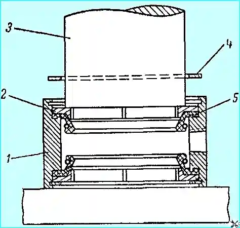
- - Identify the faulty block, remove the pivot pin and take it out.
- - If the seals are worn out, disassemble the block and replace the seals.
- - Check the tightness of the block at a pressure of 3 kg / cm².
- - When installing the block in the pivot pin, put grease in the cavity between the cuffs.
Checking the tightness of the system:
- - With the wheel valves open and the handle of the control valve in the neutral position, the fall the air pressure in the tires should not be more than 1 kg/cm² in 12 hours.
- - Check after the tires have cooled to ambient temperature.