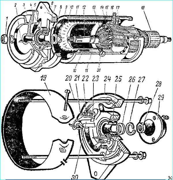
The GAZ-5ZA vehicle is equipped with a two-pole, two-brush generator G130-G (Fig. 1), and the GAZ-66 vehicle is equipped with a G130-V
Open-type direct current generators designed for a maximum current output of 28 A at a voltage of 12-15 V.
Some vehicles use G 130-E generators, which have shielded terminals.
Generator Maintenance
For easy inspection of the generator, remove the protective tape. Start the inspection with the commutator, brushes and brush holders.
In this case, make sure that the brushes are intact, do not hang in the brush holders and are in secure contact with the commutator.
Check the tension of the brush springs. As the brushes wear out, the spring tension may decrease.
The spring tension can be adjusted by bending the spring stop. Measure the brush pressure with a spring dynamometer.
Blow out the generator from the commutator side with compressed air; slightly dirty collector wipe with a clean cloth slightly moistened with gasoline.
Heavily dirty collector with slight burns and small roughness clean with glass paper of 80 or 100 grain, rotating the anchor by hand (do not use sandpaper).
For a generator with a significantly worn or burnt collector, grind the collector.
Clean the working surface of the brushes with a cloth slightly moistened with gasoline.
If there is incomplete contact with the collector, rub the brushes.
Carefully check the generator bearings for jamming. Replace seized bearings.
Generator malfunctions and troubleshooting methods
- Causes of malfunction
Remedies
No battery charge
- Brush sticking
Clean brush holders from dirt, check brush spring tension
- Commutator burning
Clean or, if necessary, grind the commutator
- Excitation circuit breakage
Solder the terminal or replace the coil
- Armature circuit breakage
Replace or repair the armature
- Interturn short circuit of the armature
Replace the defective armature.
- Armature touching poles
Check the bearings and their mounting seats, replace any damaged parts
- Unreliable contact in the shielded connectors of the G13O-E generator
Eliminate the faults by replacing the spring rings that compress the sockets of the connectors
Rapid wear of the brushes:
- Increased collector runout
Turn and grind the collector
Squeaking in the generator or abnormal noise:
- Poorly ground brushes
Grind the brushes
- No grease in the bearings
Replace the bearings
- The anchor is touching the poles
Check the bearings, mounting seats, damaged parts, replace
- Bearing wear
Replace bearings
- Bearing seizure
Replace bearings
- Bearing seat wear
Replace covers or anchor
Increased anchor axial play:
- Bearing wear
Replace bearings
Bracket and its mounting feet are broken. Frequent loosening of the generator mount:
- Increased pulley imbalance
Check the pulley imbalance, if it exceeds 25 g/cm, perform balancing
- Presence of dents on the water pump pulley
Replace the damaged pulley
Strong generator heating:
- Violation of adjustment and sintering of contacts at the voltage regulator or current limiter
Check the relay regulator and eliminate the malfunction
Generator repair
Disassemble the generator to be repaired in the following order.
Remove the protective tape and brushes.
Shine the bearing cover and unscrew the nut securing the rear end of the anchor shaft.
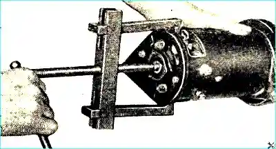
Unscrew the tension generator screws and remove the cover from the collector side using a puller (Fig. 2).
Remove the anchor with the cover from the pulley side of the housing.
Use a puller to remove the pulley from the anchor, then unscrew the bearing mounting plate screws and remove the cover.
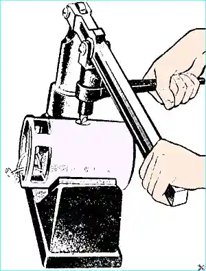
If necessary, unscrew the pole mounting screws in the device and remove the excitation coils (Fig. 3).
Inspection and testing housing
Using the 533 device or a test lamp connected to the alternating current network, check for short circuits between the excitation coils and terminals on the housing.
When checking with a test lamp, connect it to the "Ш" terminal and the housing.
Then switch the test lamp from the "Ш" terminal to the "Я" terminal. In this case, the tips disconnected from the brush holders should not touch the housing.
In both cases, the lamp should not light.
If the lamp lights, this indicates a short circuit between the excitation winding or the terminal on the housing. In this case, remove the excitation windings and repair the damage.
Replace damaged insulation gaskets and terminal bushings.
Then check the integrity of the excitation winding using a test lamp.
To do this, connect the test lamp to the "Ш" terminal and the tip of the wire from the excitation winding.
If the winding is in good condition, the lamp should light.
Check the excitation windings for interturn short circuits.
This check is performed on the 533 device. The excitation coils can be checked using an ohmmeter.
The resistance of both coils should be 7.6-8.4 ohms. Excitation coils with interturn short circuits must be replaced.
There should be no traces of the anchor touching the poles. If there is any contact, check the covers and bearings and replace if necessary.
Inspection and testing of covers
Using the 533 device or a test lamp, check for short circuit of the insulated brush holder to the cover on the collector side. If the insulation is in good condition, the lamp should not light.
The bearing should fit freely into the cover on the collector side, but without noticeable slack.
The diameter of the hole for the bearing should be 35 +0.03 mm.
If the diameter of the hole for the bearing is higher than specified or the insulated brush holder shorts, then the cover must be replaced.
Make sure that the bearing in the cover on the pulley side sits tightly (press fit). The diameter of the hole for the bearing should be 47 +0.0З mm.
Inspection and testing of the anchor. Check the generator anchor for interturn short circuits (Fig. 4), as well as short circuits of the winding to the iron package on the 533 device.
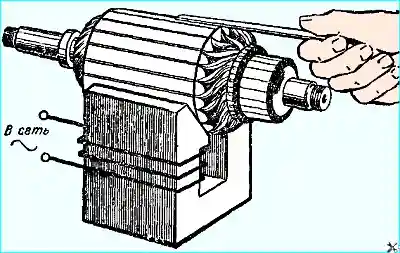
If there is damage, the anchor must be replaced.
If, upon inspection of the anchor collector, it is found that it is dirty and has traces of burning and uneven wear along its length, it should be cleaned with fine glass sandpaper with a grain size of 80 or 100.
To clean the collector, secure the anchor by the front cover in a vice and, smoothly turning the anchor, clean the collector with sandpaper.
If the collector has severe wear and runout of the surface, turn it on a special GARO machine or on a lathe.
After turning, check the collector runout with an indicator.
A collector runout higher than 0.03 mm leads to rapid burning of the collector and wear of the brushes, especially at high engine crankshaft speeds.
On the turned collector, trim the insulation to a depth of 0.8 mm in a device or with a hacksaw blade sharpened on both sides to 0.8 mm.
After trimming, polish the collector with fine glass sandpaper 100.
Inspection and checking of the brush node
To check the brushes, assemble the anchor with the cover on the collector side.
Check whether the brushes are jammed in the brush holders, as well as the condition and amount of wear of the brushes, and the pressure force of the brush springs.
If the brush pressure is weak, sparking increases and the collector burns.
Excessive pressure of the brushes causes the collector to overheat and severe wear of the brushes.
The spring pressure on the brushes should be within 800-1300 G.
When measuring the pressure, place a strip of paper under the brush, and then, while pulling the dynamometer spring, simultaneously pull the paper strip and, when the paper begins to move, record the dynamometer reading.
The brushes in the brush holders should move freely, without jamming or excess gap.
Worn to a height of 14 mm, oily or damaged brushes should be replaced with new type E brushes G1Z or EG1Z-P measuring 22.3x23.5x6.3 mm.
Brushes of another type cannot be used.
In case of replacing brushes or boring the collector, it is recommended to grind the brushes to the collector. Place a strip of sandpaper on the collector with the abrasive side facing the brush.
By turning the anchor by hand in the direction opposite to the anchor rotation, achieve grinding of the brush over the entire working surface.
When turning the anchor in the opposite direction, slightly lift the brush using a hook.
After completing the inspection and replacing defective parts, assemble the generator in the reverse order of disassembly. After assembly, check the generator.
Checking the generator
The generator's serviceability and correct assembly are determined by:
- - checking the generator in electric motor mode;
- - checking the number of revolutions per minute at which a voltage of 12.5 volts is achieved when the generator is idling and at full load.
To check the generator running idly, it must be connected to the 12 V battery circuit and the consumed current must be measured.
Connect the generator body to the negative terminal of the battery, and the "Ya" and "Sh" terminals to its positive terminal (Fig. 5).
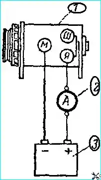
To check the G130-E generator, you need to have additional terminal connectors.
It is very important not to mix up the wires when connecting, since if the polarity is not observed, the generator will be remagnetized.
Installing a remagnetized generator on a car can lead to the sintering of the contacts of the reverse current relay and to the failure of the relay-regulator.
The consumed current must be measured after the generator has been running for five minutes.
A serviceable generator should consume a current of no more than 6 amperes at 550 - 700 rpm.
In this case, its anchor should rotate clockwise (from the drive side) smoothly, without jerking.
Jerking of the anchor when approaching the brushes of the same collector plates are usually a sign of a faulty generator armature winding.
When the generator is running with an electric motor, sparking under the generator brushes should be barely noticeable.
If the sparking is strong and traces of burning remain on the collector, this means that the generator windings are faulty.
Increased current consumption and simultaneously low speed characterize incorrect assembly (distortion of covers, armature touching the poles).
Increased current consumption and simultaneously high speed usually indicate the presence of faults in the electrical part of the generator.
Lower current consumption indicates poor contacts in the armature circuit (dirty collector or brushes, weak pressure of the brushes on the collector, poor contacts at the joints).
The number of revolutions at which the generator develops a voltage of 12.5 V is checked on a test bench consisting of an electric motor that allows for smooth change of the generator anchor speed (up to 3000 rpm), instruments (voltmeter, ammeter and tachometer) and a rheostat that allows for creating a load of up to 30 amperes in the generator circuit.
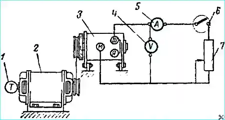
The generator connection diagram for testing on the simplest stand is shown in Fig. 6.
Without load, when the generator is cold, the voltmeter should show 12.5 V, at 1450 rpm (no more) of the generator anchor.
With a load of 28 A and a voltage of 12.5 V, the number of revolutions of the generator anchor should be no more than 2400 rpm.
During the test, change the generator anchor revolutions smoothly and monitor the voltmeter and ammeter readings, preventing excessive increase in voltage and current in the circuit, so as not to damage the generator.