Two cylinder heads are installed on the engine. Each head is centered by two locking pins pressed into the cylinder block
Guide bushings and valve seats are pressed into the cylinder heads.
Valve bushings are metal-ceramic. The inner diameter of the intake valve sleeve is 9 +0.022 mm, and the exhaust valve is 11 +0.022 mm.
The permissible wear of the valve guide bore should not exceed 0.05 mm. If the inner diameter of the bushing increases further, it should be replaced.
For spare parts, valves are produced in a standard size, and bushings are produced with an internal diameter reduced by 0.3 mm, i.e., with an allowance for expansion after pressing into the cylinder head.
The worn bushing is pressed out using a drift. The new bushing is pressed in using a thrust mandrel from the rocker arm side.
The bushing above the plane under the valve spring should protrude no more than 22 mm.
After pressing, the valve sleeve hole is reamed to the appropriate standard size.
Valve seats are made of cast iron.
Minor defects in the working surface of the seat can be eliminated during the process of lapping the valve to the seat, and deep scratches and other large defects can be eliminated by grinding the seat and then lapping the valve to the seat.
The tight fit of the valve in the seat also depends on the concentricity of the working chamfer of the seat and the hole in the guide sleeve.
The concentricity of the saddle is measured with an indicator device.
The base is the hole in the valve guide, and the indicator leg slides along the working surface of the seat.
Non-concentricity acceptable without repair should not exceed 0.06 mm.
When replacing, valve seats are removed using carbide countersinks.
Before installing a repair-size seat, its seat in the cylinder head is bored to the following dimensions:
For the intake valve seat 49.25 +0.027 mm and exhaust - 38.75 +0.027 mm.
Before being pressed into the cylinder head, valve seats and guides are cooled in solid carbon dioxide (dry ice), and the cylinder head is heated to 160-175°C.
Cold seats and bushings during assembly should fit into the sockets of the heated cylinder head freely or with little effort.
By lightly hitting the mandrel with a hammer, the valve seat and valve sleeve should snap into place.
Under no circumstances should the seat or bushing be hammered in with great force, as this will disrupt the fit, and later when the engine is running, the seat or bushing may fall out of its seat.
The operation of installing seats and bushings into the cylinder head must be performed quickly.
When the temperatures are equalized, large tensions appear in this connection, at which further pressing is impossible without great effort.
Grind the working chamfers of the newly installed seats concentrically with the holes in the valve guides. A special device is used for this.
The expanding guide is installed in the machined hole of the sleeve, and the shank of the guide serves as an axis for the grinding wheel (drive from an electric motor) with a chamfer at an angle of 45°.
When grinding, the concentricity of the working chamfer of the seat and the valve sleeve hole must be 0.03 mm (according to the indicator).
The cylinder head arriving for assembly must be thoroughly washed, the cooling jacket must be cleaned of scale and dirt, the oil channels must be cleared of sludge, and the exhaust channels must be cleared of carbon deposits.
Valve guides pressed into the block head must be of nominal or one of the repair sizes and marked with paint. The dimensions of the bushings and their markings are indicated in the table. 1.
The distance from the upper end of the guide sleeve to the plane of the head should be 24 mm.
Intake and exhaust valve seats must be ground at 45° to the axis of the guide bushings.
The width of the working chamfer of the seat should be 1.5 - 2.0 mm.
The runout of the conical surfaces of all valve seats relative to the axes of the valve guide holes is no more than 0.025 mm.
Valve guides pressed into the cylinder head along the outer diameter can be of nominal size or repair size (increased by 0.25 mm).
Table 1. Nominal and repair dimensions of the valve guide
- Nominal size, marking - yellow, inner diameter of valve guide - 9.00 +0.022 mm;
- First repair, reduction in diameter by 0.20 mm, marking - white, internal diameter of the valve guide - 8.80 +0.022 mm;
- Second repair, increase in diameter by 0.20 mm, marking - green, internal diameter of the valve guide - 9.20 +0.022 mm
Intake and exhaust valves
The diameters of the valve stems must be nominal or one of the repair sizes in, given in the table.
Table 2. Nominal and repair dimensions of valve stems
- Nominal size, marking - yellow, intake valve stem diameter - 9.0 -0.050 mm, exhaust valve stem diameter - 9.0 -0.075 mm;
- First repair, diameter reduction by 0.20 mm, marking - white, intake valve stem diameter - 8.80 -0.050 mm, exhaust valve stem diameter - 8.80 -0.075 mm;
- Second repair, increase in diameter by 0.20 mm, marking - green, intake valve stem diameter - 9.2 -0.050 mm, exhaust valve stem diameter - 9.2 -0.075 mm
The working chamfer of the valve head must be ground at an angle of 45° to the axis of the stem.
The cleanliness of the working surface of the chamfer after grinding must correspond to class 8.
Runout of the working surface of the chamfer relative to the valve stem is no more than 0.03 mm.
Assembling and installing the cylinder head
Before installation, valves and guide bushing holes must be thoroughly wiped.
Valves with stems of nominal or repair sizes must be installed in guide bushings of the appropriate size.
Before assembly, the valves must be ground into the seats in the cylinder head.
Lapping should be done with a paste consisting of one part of micropowder M20 GOST 3647-59 and two parts of industrial oil 20 (spindle).
After grinding in, the working chamfers of valves and seats must have a continuous matte contact strip along the entire circumference with a width of at least ½ the width of the seat chamfer.
Lapped valves are numbered by their seats and are not de-identified afterwards.
After grinding in, the parts must be washed thoroughly.
The quality of the grinding must be checked for tightness (at an excess pressure of 0.05 kg/cm² the amount of air passed through the valve can be no more than 12 cm³ in minute).
The order of placement of the studs for fastening the rocker arm axle struts and the exhaust pipeline:
a) post studs M10x1 L = 112 mm - two outer ones;
post studs M10x1 L = 80 mm - two middle ones;
b) intake manifold mounting studs:
- extreme M10x1 L = 30 mm;
- medium M10x1 L = 42 mm.
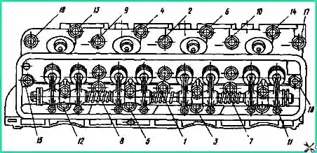
Before installing the cylinder head assembly with valves and exhaust pipe, the head mounting studs must be screwed into the block completely in the order shown in Fig. 1 and table.
The cylinder head gasket must not have cracks or asbestos chipping.
Before installation, the head must be thoroughly blown with compressed air.
The cylinder head must be freely placed on the studs without impacts and installed on two pins.
When tightening the cylinder head stud nuts, adhere to the order shown in Fig. 1.
The nuts are tightened in two stages, preliminary and final.
The tightening torque should be in the range of 7.3-7.8 kgm.
Final tightening must be done on a cold engine.
After a hot run-in and complete cooling of the engine, check the tightening torque, which should be 7.3-7.8 kgm.
When tightening the cylinder head nuts, loosen the intake manifold nuts.
Table 3. Installation order of cylinder head studs
Number of studs in order / size of stud and its number:
- 12-5-3-11 / 291859-P; M11x1L=170;
- 3-1-7-16 / 291860-P; M11x1L=208;
- 17-10-2-9-18 / 291826-P; M11x1L=195;
- 13-4-6-14 / 291823-P; M11x1L=108;
- 15 in the right row of the cylinder / 291826-P; M11x1L=208;
- 15 in the left row of the cylinder / 291826-P; М11х1L=195
Assembling and installing an axle with rocker arms and struts
Before assembly, thoroughly clean the internal cavity of the rocker arm axle from sludge, dirt, etc. and blow with compressed air. Wipe the outer surface with a napkin and lubricate with a thin layer of spindle oil.
The assembled rocker arms on the axle should rotate freely without jamming.
The adjusting screw should screw into the rocker arm freely without jamming.
Install the rocker arm axles with rocker arms and struts assemblies onto the block head studs so that the heads of the pusher rods fit into the rocker arm sockets.
The gap between the valves and the rocker arm on a cold engine should be within 0.25-0.30 mm.
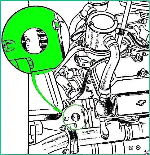
Adjust the gap in the following order: turn the crankshaft to the position corresponding to c. m.t . compression stroke in the first cylinder, for which:
- - close the hole for the spark plug of the first cylinder with your finger, turn the crankshaft until compressed air begins to escape from under the finger. This will happen at the beginning of the compression stroke;
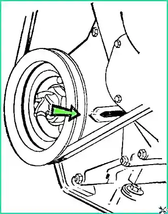
- - carefully rotate the crankshaft until the marks on the crankshaft pulley coincide with the central mark of the pointer c. m. t. (Fig. 2), located on the front cover of the block, and adjust the gaps between the valves and rocker arms of the first cylinder.
Then, turning the crankshaft 90˚ each time, adjust the valve clearances of the remaining seven cylinders in the order of their operation 5-4-2-6-3-7 and 8.