GAZ-66 car compressor
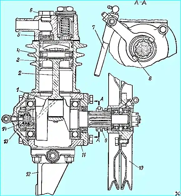
GAZ-66 cars are equipped with a compressor (Fig. 1), designed to inflate tires with air.
Compressor features:
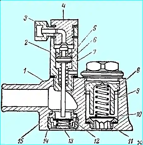
Compressors of cars with a tire pressure regulation system (GAZ-66-01, GAZ-66-02, GAZ-66-04, GAZ-66-05) differ from compressors of cars without this system (GAZ-66 and GAZ-66-03) in that a relief cylinder is screwed into the threaded hole of the compressor head above the inlet valve instead of a plug (Fig. 2).

**Compressor (Fig. 1):**
1. Crankshaft.
2. Connecting rod.
3. Piston.
4. Cylinder.
5. Cylinder head.
6. Plug.
7. Roller.
8. Fork.
9. Engagement clutch.
10. Pulley.
11. Crankcase.
12. Bracket.
13. Spring.
14. Seal.
Description of compressor:
The compressor is piston type, single-cylinder, air-cooled. It is driven through a pulley together with the power steering pump by two belts from the engine crankshaft pulley.
The compressor engagement clutch is installed on the splines of the compressor crankshaft. The coupling is moved by a fork mounted on a shaft, the position of which is fixed by a ball lock.

Fig. 2. Compressor head:
1. Head housing.
2. Unloader cylinder housing.
3. Coupling.
4. Fitting.
5. Sleeve.
6. Piston.
7, 9, 13. Springs.
8. Plug.
10. Discharge valve.
11, 16. Seats.
12. Inlet valve.
14. Inlet valve housing.
**Operating principle:**
Air enters the compressor from the engine air filter. Lubrication comes from the car engine.
**Compressor maintenance:**
- Periodically check the tension of the compressor belts. The belts are tensioned by tilting the power steering pump.
- The tilt angle of the pump should ensure that the oil is filled to the "oil level" mark on the pump reservoir, and if there is no mark, to the filler filter of the reservoir.
- If the tilt does not ensure the belt tension, move the pump.
- If the belts are very stretched, move the pump brackets to the additional holes in them.
- The tension is considered normal if, when you press your finger on the belts between the pulleys of the pump and the engine crankshaft, the belts bend by 15-20 mm.
**Compressor malfunctions and how to fix them:**
- 1. **Reduced performance:**
- Air leak through valves or piston rings.
**Remedy:** Repair the compressor.
- The compressor air filter is clogged (for vehicles without a tire pressure regulation system).
**Remedy:** Wash the filter packing.
- Loose drive belt tension.
**Remedy:** Adjust the belt tension. - 2. **The compressor is overheating:**
- Poor oil supply.
**Remedy:** Clean the oil lines and channels in the crankcase cover and compressor crankshaft.
- Carbon deposits on the piston and piston rings.
**Remedy:** Clean the parts from carbon deposits. - 3. **Oil ejected with the compressed air:**
- Wear of piston rings or cylinder.
**Remedy:** Repair the compressor.
- Damage to the seal of the oil supply to the compressor.
**Remedy:** Replace seal 14 (see Fig. 1) or the rear cover of the compressor.
- Broken seal spring.
**Remedy:** Replace the spring.
- Clogged oil drain tube.
**Remedy:** Clean the tube. - 4. **Increased compressor knocking:**
- Wear of pistons, pins or bearings.
**Remedy:** Repair the compressor.
Compressor repair:
- 1. **Removing and disassembling the compressor:**
- Disconnect the oil drain and supply pipes, the supply hose and the air drain pipe.
- Remove the compressor from the engine.
- Remove the pulley 10 (Fig. 1) of the compressor with the bearings in assembly.
- Unscrew the locking screw of the compressor fork, remove shaft 7 and fork 8 of the compressor.
- Remove the clutch 9 of the compressor.
- Remove the compressor head and bracket 12.
- Remove the connecting rod cover and remove piston 3 with connecting rod 2 in assembly from cylinder 4.
- Remove the front and rear covers, remove the seal 14 and the spring 13 from the crankshaft seat.
- Remove the compressor cylinder.
- Press off the crankshaft bearings and take out crankshaft 1.
- Unscrew plug 8 (see Fig. 2) of the discharge valve, remove spring 9 and valve 10.
- Unscrew seat 11.
- Unscrew valve body 14 and take out spring 13, valve 12 and valve seat 15.
- Unscrew plug 6 (see Fig. 1) or the unloading cylinder; take out the piston pin and separate the piston from the connecting rod.
- Remove the piston rings.
2. **Checking the technical condition and repairing compressor parts:**
- If the cylinder wear exceeds the permissible limit or its surface is damaged, repair the cylinder to one of the repair dimensions specified in the table. 2.
- Pistons and piston rings of repair sizes are produced according to these dimensions.
- The piston repair size group is indicated by numbers on the piston bottom: "+0.4", "+0.8".
- Piston rings of repair size are marked:
- One stripe with a width of 10 mm corresponds to an increase in the ring diameter compared to the nominal by 0.4 mm.
- Two stripes - by 0.8 mm.
- When repairing the crankshaft, use liners of repair sizes, the thickness of which is increased by 0.15 and 0.3 mm.
- The group of the repair size of the liner is indicated by numbers on its outer side: "-0.3" and "-0.6" (these liners have a thickness of 1.9–0.013 mm and 2.05–0.013 mm).
- If nicks or annular grooves are found on the plate valves of the cylinder head, replace them and grind new valves to the seats to obtain continuous annular contact.
- Piston pins, pistons and connecting rods are divided into four groups, which are sorted by the diameters of the mating surfaces through 0.003 mm (Table. 3).
- Marking locations:
- Piston — on the boss under the pin.
- Piston pin — on the pin plug.
- Connecting rod — on the head under the piston pin.
- During assembly, it is allowed to install the pin and connecting rod of the adjacent group.
- Pins for the connecting rod and piston are selected without lubrication at a temperature of 10–30°C. The correct selection of the piston pin to the connecting rod bushing is checked by touch. When pressed with the thumb, the piston pin without lubrication should move with some resistance in the bushing of the upper connecting rod head.
3. **Assembling the compressor:**
- When assembling the piston with the pin-connecting rod kit, lubricate the pin with clean engine oil.
- When installing new rings, check the lock clearance after installation in the cylinder. The clearance should be 0.20–0.40 mm, and the ring should fit tightly to the cylinder along the entire circumference (check for clearance).
- Check that the ring height and piston groove match. The gap between the groove wall and the ring should be within 0.035–0.080 mm.
- If the gap is smaller and the ring does not roll along the entire piston groove, the end of the ring can be slightly ground down on the finest sandpaper.
- Install the compression rings in the piston grooves with the undercuts facing up, and spread their joints by 180°.
- During compressor assembly, check the ease of rotation of the crankshaft. The torque required to turn it must not exceed:
- 0.2 kgf m — before installing the connecting rod and piston group.
- 0.3 kgf m — after installing this group and tightening the connecting rod bolts (but before installing the head).
- When installing the inlet valve seat, ensure that the narrower belt of the seat faces the valve.
- Through the upper opening of the head, check the valve stroke, which should be within 0.7–1.5 mm, and the discharge valve — within 1.5–3.2 mm.
**Compressor tests after repair:**
1. **Running-in (without load):**
- Conducted for 20 minutes at 1200–1350 rpm of the crankshaft.
- The pressure of the oil entering the compressor must be 1.5–3.0 kgf/cm², the temperature must not be lower than +40°C.
- The air pressure cooling the compressor must ensure that the compressor head temperature does not exceed 90°C.
2. **Performance test:**
- Conducted at 1200–1350 rpm of the crankshaft and with air pumped into a 23-liter tank.
- At a tank pressure of 6.5 kgf/cm², the tank cavity communicates with the atmosphere through a calibrated hole with a diameter of 1.0 mm and a length of 3 mm.
- Under these conditions, the compressor must maintain a pressure in the tank of at least 6 kgf/cm² during continuous operation for 3 minutes.
- At the specified compressor operating mode, the ejection of oil with the pumped air must not exceed 1 cm³ in 5 minutes.
3. **Tightness test:**
- Conducted on a non-working compressor by supplying air under a pressure of 5–5.5 kgf/cm² to the discharge pipe of the compressor head from a 1 l tank.
- The pressure drop in the cylinder should be no more than 0.3 kgf/cm² within 1 min.
4. **Checking the operation of the unloading system (for compressors with an unloading cylinder):**
- Supply compressed air under a pressure of 5–5.5 kgf/cm² to the unloading cylinder.
- The piston of the unloading cylinder should go down and fully open the inlet valve.
- At the same time, check the tightness of the seal of the piston of the unloading cylinder.
- The pressure drop in a 1 l tank at a pressure of 5–5.5 kgf/cm² should not exceed 0.25 kgf/cm² within 1 min.
- When the pressure is released, the piston, under the action of the return spring, should clearly return to its original position.
**Table 2. Nominal and repair dimensions of the compressor cylinder and piston, mm:**
| Size name | Deviation from nominal size | Cylinder diameter | Piston diameter |
|---|---|---|---|
| Nominal | 0.0 | 60+0.030 | 60-0.030 |
| 1st renovation | +0.4 | 60.4+0.030 | 60.4-0.030 |
| 2nd renovation | +0,8 | 60,8+0,030 | 60,8-0,030 |
**Table 3. Dimensions and marking of pistons, pins and connecting rods by groups:**
| Group number | Marking color | Piston diameter | Piston pin diameter | Connecting rod diameter |
|---|---|---|---|---|
| I | White | 12,503–12,500 | 12,500–12,497 | 12,507–12,504 |
| II | Green | 12,500–12,497 | 12,497–12,494 | 12,504–12,501 |
| III | Blue | 12,497–12,494 | 12,494–12,491 | 12,501–12,498 |
| IV | Red | 12,494–12,491 | 12,491–12,488 | 12,498–12,495 |


