Repair and inspection of the power steering pump, control valve and power cylinder
To repair or inspect the condition of the parts, it is necessary to disassemble the power steering pump, control valve and power cylinder.
Disassembling and checking the power steering pump
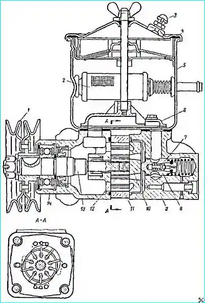
Before disassembling, the pump (Fig. 1) must be removed from the car, drain the oil, clean and wash the outer surface of the pump.

- Fig. 1. Power steering pump:
1. Pulley.
2. Filter.
3. Breather.
4. Reservoir cover.
5. Reservoir.
6. Manifold.
7. Safety valve.
8. Bypass valve.
9. Pump cover.
10. Distributor disk.
11. Stator.
12. Rotor.
13. Shaft.
14. Pump body.
Pump disassembly and inspection procedure:
- 1. Remove the reservoir cover and filters.
2. Remove reservoir 5.
3. Install the pump so that its shaft is vertical and the pulley is at the bottom, and remove the cover 9 of the pump. When removing the cover, hold the bypass valve 8 to prevent it from falling out.
4. Mark the position of the distribution disk relative to the stator 11 and remove it from the pins.
5. Mark the position of the stator 11 relative to the pump housing 14 and remove the stator (the arrow on the stator indicates the direction of rotation of the pump shaft).
6. Remove the rotor 12 together with the blades. The stator, rotor and blades of the pump are individually selected at the factory, so their completeness must not be violated during disassembly.
7. Remove the pulley 1 (if necessary), the retaining ring and the shaft 13 of the pump together with the front bearing.
8. Check the free movement of the bypass valve in the pump cover and the absence of nicks or wear. The valve and pump cover are individually selected at the factory, so their completeness must not be violated during disassembly.
9. Check the tightness of the seat of the safety valve 7 and tighten it if necessary.
10. Check the channels of the pump parts and clean them.
11. Check for scoring or wear on the end surfaces of the rotor, housing and distribution disk. In case of minor scoring or wear, grind these surfaces on the plate, then thoroughly wash the parts.
12. Check whether the blades 4 move freely in the grooves and whether they are worn.
13. Inspect the rubber seals. Replace hardened, cracked and other defective seals.
The technically sound condition of the pump is determined by two indicators:
- The maximum pressure that the pump creates.
- Noise during operation.
**Note:**
Wear of individual parts, except for obvious scoring, cannot serve as grounds for their replacement. During assembly at the factory, the rotor, stator and blades are sorted into three groups by length. Only parts of one group are installed in the pump. When repairing the pump, the rotor, stator and blades are also replaced as a set.
**The dimensions for sorting the rotor, stator and blades are given in Table 1.**
**The bypass valve spool and the pump cover are also selected as a set, sorting into three groups by the diameters of the hole and neck. The dimensions for sorting are given in Table 2.**
**If the pump is noisy:**
Replace the ball bearing of the pump shaft.
**Note:**
The pump is unified with the pump of the ZIL-130 vehicle, except for the pulley and the spring of the bypass valve.
Assembling the power steering pump
- 1. Before assembly, thoroughly wash and dry all parts. Do not wipe the parts with ends and rags that leave threads, lint, etc. on the parts.
2. Install the stator, rotor with blades and distribution disk in accordance with the marks made during disassembly and the arrow indicating the direction of rotation. The chamfer of the splined hole should face the pump body.
3. Install the cover with the bypass valve. The hexagon of the seat must face the inside of the hole.
4. Tighten the cover mounting bolts evenly. Tightening torque of the bolts: 2.1–2.8 kgf m.
5. Tightening torque of the bolts securing the reservoir: 0.8–1 kgf m.
6. Tightening torque of the nut securing the pump pulley: 5–6.5 kgf m.
7. The pump shaft must rotate freely, without jamming.
Disassembling the control valve
- 1. Drain the oil from the power steering system.
2. Disconnect the pipes and hoses from the control valve.

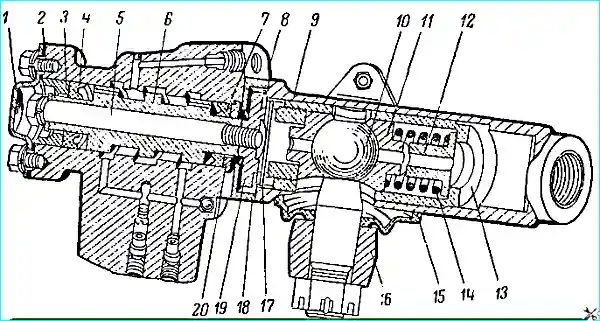
Fig. 2. Power steering control valve:
- 1. Cover.
2. Gasket.
3. Gold ika.
4. Sleeve.
5. Valve spool mounting bolt.
6. Valve spool.
7. Sleeve.
8. Control valve body.
9. Longitudinal tie rod end.
10. Ball pin.
11. Ball pin cracker.
12. Limiter.
13. Cup.
14. Spring.
15. Pin seal.
16. Steering arm.
17. Pin.
18. Adapter.
19. Nut.
20. Cover.
- **Disassembly procedure:**
1. Remove cover 1 of the control valve.
2. Unscrew central bolt 5.
3. Unscrew the bolts securing the control valve body to the longitudinal rod and remove the control valve.
4. Unscrew the adapter mounting screw and remove adapter 18.
5. Remove the covers and cuffs on both sides of the valve.
6. Remove spool valve 6.
7. If the bronze seats are heavily dented and deformed, press them out and press in new ones. - **Determining the technical condition of the valve parts:**
- There should be no nicks, scoring or deep scratches on the working journals of the spool valve. If necessary, clean with a finishing block, without rolling up sharp edges.
- The spool valve should move freely in the valve body without jamming. Clean the two holes in the spool valve necks.
- Sealing cuffs 4 and 7 should remain elastic, without cracks, snags or other defects.
- Thoroughly flush the internal cavities and channels of the valve body.
**Note:**
The spool valve and valve body are sorted into three groups by the diameter of the necks and holes. The dimensions of the parts by groups are given in Table 3.
Assembling the control valve
- 1. Install adapter 18 on the longitudinal rod and tighten its fastening screw. Make sure that there are no nicks or dirt on the mating ends.
2. Assemble valve spool 6, seals 4 and 7, and covers 3 and 20 in the valve body.
3. Lubricate the valve spool and seals with turbine or spindle oil before installation.
4. Insert the spool into the body without distorting it, without applying force.
5. Assemble the valve body and spool by the mating diameter of only one group.
6. Make sure that the outer neck of the larger diameter spool faces the longitudinal rod.
7. Finally tighten the valve body fastening bolts after tightening central bolt 5.
8. Check the freedom of movement of the spool in the body.
9. Install cover 1, replacing cork gasket 2.
10. If the hoses are not immediately connected to the valve, plug the connection points with plugs.
Disassembling the power cylinder
Before disassembling the power cylinder, it is recommended to check the freedom of movement of the rod with the piston from one extreme position to another.

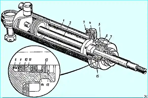
- Fig. 3. Power steering cylinder:
1. Cylinder.
2. Rod with piston.
3. Nipple.
4. Nipple bolt.
5. Head fastening lock nut.
6. Head fastening nut.
7. Cylinder head.
8. Seal spring.
9. Spring cup.
10. Seal.
11. Cover.
12. Adjusting washers.
13. Retaining ring.
14. Felt oil seal.
15. Sealing rings. - **Disassembly procedure:**
1. Loosen lock nut 5.
2. Unscrew nut 6 securing head 7 of cylinder.
3. Remove head 7 from cylinder together with rod 2.
4. Remove the piston rod from the head.
5. If the ball joint is worn out, disassemble the joint and replace the worn parts. - **Determining the technical condition of the cylinder parts:**
- There should be no scoring on the inner surface of the cylinder.
- The piston rings should fit around the entire circumference of the cylinder or to a cylindrical gauge with a diameter of 50 mm.
- The piston rings should rotate freely in the piston grooves.
- There should be no wear on the chrome surface of the piston rod.
- There should be no scoring in the hole for the piston rod in the cylinder head 7.
- Brass washers 12 should not be deformed.
- Rubber cuff 10 should be elastic and undamaged.
- Felt seal 14 should compress the piston rod. If the seal is dirty or does not compress the rod, it must be replaced.
- The rubber sealing rings on the cylinder head must remain elastic.
Assembling the power cylinder
- 1. Lubricate the rod with the piston and the inner surface of the cylinder with turbine or spindle oil during assembly.
2. Install the piston rings on the piston with the locks in different directions.
3. Screw nut 6 for fastening the cylinder head until it stops against the end of the cylinder and lock it with lock nut 5.
4. Check the freedom of movement of the rod in the cylinder. The rod must move evenly, without jamming, under slight force (no more than 6 kgf).
5. If there is a unit, check the cylinder for oil leakage through the piston rings. Normal oil leakage should not exceed 360 g per minute.
Dimensions tables
**Table 1. Dimensions of the rotor, stator and blades by groups:**
| Part name | Group number | Part length, mm |
|---|---|---|
| Rotor | 1 | 22,000–21,996 |
| 2 | 21,996–21,992 | |
| 3 | 21,992–21,988 | |
| Stator | 1 | 22,017–22,013 |
| 2 | 22,013–22,009 | |
| 3 | 22,009–22,005 | |
| Blade | 1 | 21,998–21,992 |
| 2 | 21,992–21,988 | |
| 3 | 21,988–21,984 |
**Table 2. Cover and neck hole diameters of the valve core by groups:**
| Part name | Group number | Diameter, mm |
|---|---|---|
| Cover | 1 | 20,015–20,010 |
| 2 | 20,010–20,005 | |
| 3 | 20,005–20,000 | |
| Zolodnik | 1 | 19,992–19,987 |
| 2 | 19,987–19,982 | |
| 3 | 19,982–19,977 |
**Table 3. Diameters of the bore and neck of the valve spool and body by groups:**
| Size name | Group number | Diameter, mm |
|---|---|---|
| Hole in the body | 1 | 27,012–27,008 |
| 2 | 27,008–27,004 | |
| 3 | 27,004–27,000 | |
| Large spool journals | 1 | 27,003–26,999 |
| 2 | 26,999–26,995 | |
| 3 | 26,995–26,991 |


