Disassembling the axle assembly with brakes and hubs (GAZ-53A).
- 1. Remove the axle shafts using the dismantling bolts.
- 2. Remove the axle shaft flange gasket.
- 3. Remove the brake drum with the hub assembly.
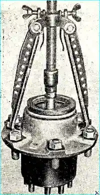
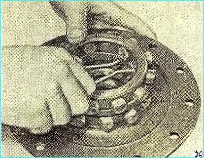
- 4. Remove the oil seal, thrust washer and inner hub bearing (Fig. 1).
- 5. Remove the brake assembly and oil deflector.
- 6. Unscrew the bolts securing the gearbox to the rear axle housing.
- 7. Remove the gearbox.
- 8. Unscrew the breather.
Disassembling the GAZ-66-02 rear axle with brakes and hubs in assembly
- 1. Remove the axle shaft flange cover and gasket, take out the axle shaft.
- 2. Remove the hub with the drum, the inner hub oil seal and the thrust washer.
- 3. Remove the hub bearings.
- 4. Remove the protective sleeve from the brake disc and the protective sleeve from the outer oil seal housing.
- 5. Remove the outer hub oil seal, brake shoes, journal assembly with the oil seal block and gasket.
- 6. Unscrew the flexible hose from the oil seal block and disconnect the oil seal block and the journal.
- 7. Remove the gearbox using the dismantling bolts.
Disassembling the rear axle gearboxes of GAZ-53A and GAZ-66 vehicles
- 1. Unscrew the oil scraper plug, remove the locking plate.
- 2. Remove the tube, spring, and plate from the oil channel.
- 3. Loosen the driven gear stop adjusting screw.
- 4. Remove the locking plates and differential bearing caps.
- 5. Remove the outer rings of the differential bearings and their adjusting nuts.
- 6. Remove the differential assembly from the housing.
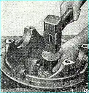
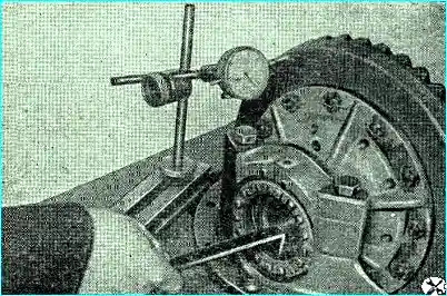
- 7. Remove the drive pinion shaft assembly from the gearbox housing (Fig. 2).
- 8. Remove the adjusting shims from the housing filler.
- 9. Remove the propeller shaft flange, the differential front cover and the gasket.
- 10. Remove the bearing sleeve together with the front roller bearing inner race.
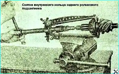
- 11. Remove the spacer ring, adjusting shims and the inner ring of the rear roller bearing (Fig. 3).
- 12. Press out the pinion shaft seal from the front differential cover.
If the outer ring of the pinion shaft tapered bearing is unusable, it must be removed.
Disassembling the differential of the GAZ-53A vehicle
Remove the driven gear from the satellite box, disconnect the oil catch can
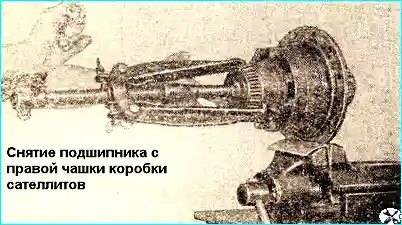
Remove the bearings differential (Fig. 4)
Remove the pinion box bolts, disconnect the pinion box, remove the thrust washers, pinions, axle gears and crosspiece
Disassembling the differential of the GAZ-66 vehicle
Disconnect the cup and the differential separator.
Remove the driven gear.
Remove the inner race of the differential bearing from the cup.
Take out the outer and inner sprockets.
Remove the inner retaining ring (Fig. 5) and crackers and remove the outer retaining ring from the separator.
Remove the inner race of the differential bearing from the separator.
Determining the technical condition of parts
The general requirements for the technical condition of the rear axle parts are similar to the requirements for the condition of the gearbox parts.
Gears. Inspect the teeth of the drive and driven gears and check if there are any scoring or signs of excessive wear.
Worn gears cannot be restored. Gears with scoring are also not suitable for further operation.
Inspect the teeth and bearing surfaces differential gears. Wear of the axle gear journal can cause increased noise during axle operation.
Worn splines, bearing surfaces or support washers cause a large gap in the transmission.
Bearing outer rings. Inspect the bearing rings for scoring or signs of uneven wear.
Check the tightness of the bearing fit between the ring and its thrust flange with a feeler gauge; a 0.03 mm thick feeler gauge should not pass through.
Bearing inner ring and rollers. Check the roller end faces for wear.
Stepwise wear of the roller ends indicates insufficient pre-tightening of the bearings or a slight skew of the rollers.
If there are no tarnishing colors or scoring, bearings with such rollers can be used.
The defective signs specified for gearbox bearings also apply to rear axle bearings.
Differential bearing adjusting nuts. Temporarily install the bearing cover and check the screwing in of the nuts.
The ends of the nuts that contact the bearings must be perpendicular to the thread axis. The runout of these ends relative to the thread axis is no more than 0.03 mm.
The surface of the ends must be clean. Make sure that the bearing covers are installed on the side on which they were machined.
Carshaft flange. The flange ends that contact the front bearing of the drive pinion shaft and the washer must be smooth and meet class 6. The non-perpendicularity of these ends to the spline hole axis must not exceed 0.05 mm.
Checking the runout of the driven gear. Check the runout of the driven gear as shown in Fig. 6. Permissible runout 0.15 mm.
If the check reveals that the runout exceeds the specified value, then it can be assumed that the gear is deformed, the satellite box is damaged, or the bearings are excessively worn. Replace unsuitable parts.
Assembling the rear axle
The rear axle is assembled in the reverse order of disassembly. In this case, it is necessary to take into account the following.
When subassembling the pinion shaft with a cylindrical bearing, insert the bearing retaining ring into the groove and compress it.
When repairing the bearing coupling, it should be taken into account that at the factory, after boring the bearing seats and pressing the outer bearing rings into them, the coupling is machined on the basis of these rings.
Therefore, when repairing the bridge, if possible, use the coupling without pressing out the outer bearing rings.
Press the inner ring of the rear roller bearing of the pinion shaft until it stops against the end face of the toothed rim.
A 0.03 mm thick feeler gauge should not pass between the ends of the rim and the bearing.
When subassembling the pinion shaft, the thickness of the adjusting lining pack is selected approximately.
Adjusting linings are installed between the ends of the inner ring of the rear roller bearing and the spacer ring.
Before assembling the differential of the GAZ-53A vehicle, the rubbing surfaces of the differential parts are lubricated with hypoid grease.
The inner rings of the differential bearings are pressed onto the journals of the satellite box until they stop.
A 0.03 mm thick feeler gauge should not pass between the ends of the bearings and the satellite box.
The bolts securing the driven gear to the satellite box are tightened (torque 7-11 kgm).
The spherical recesses on the support washers of the axle shaft gears must face the gears.
The right and left cups of the satellite box are connected so that the numbers indicated on them were identical and located opposite each other.
After assembling the differential, check the rotation of the differential gears by the axle gear using a spline mandrel. It should be smooth, without jamming.
Assembling the differential of the GAZ-66 vehicle
- 1. Before assembling, lubricate the differential parts with hypoid grease.
- 2. Install the outer retaining ring on the separator until it stops against the flange. Place the crackers in the holes so that the protrusions on the crackers rest against the retaining rings.
- 3. Install the inner retaining ring between the rows of crackers, having previously compressed it. At the same time, ensure that the crackers slide freely (under their own weight) in the separator holes.
- 4. Insert the inner sprocket into the separator.
- 5. Install the inner row crackers (from the side of the journal under the bearing) on the cams of the inner sprocket so that the radius projections of the crackers are on the same circle, and the crackers of the outer row are located so that six crackers enter the cavities of the sprocket, and six crackers stand on its projections.
- 6. Install the outer sprocket of the differential on the crackers inserted into the separator.
Side clearance in the engagement of the crackers and sprocket cams in a new differential should be within 0.3-1.6 mm, measured at a radius of 62 mm.
The assembled differential is checked for contact between the crackers and sprockets. The contact area of the crackers should be at least 75%.
To check the lateral clearance and contact, brake one sprocket, for example the outer one, with a mandrel inserted into its splined hole, and turn the other (inner) sprocket from one extreme position to another using a splined mandrel.
Before checking the contact, coat the working surfaces of the cams with a thin layer of paint.
Press the inner races of the differential bearings onto the cup and separator until they stop against the shoulders on the journals; in this case, a 0.03 mm thick feeler gauge should not pass between the ends of the bearings and the support flanges on the cup and separator.
Tighten the bolts securing the driven gear to the cup and separator (torque 7-11 kgm).
Assembling the gearbox
Install gaskets with a total thickness of 1.5 mm between the ends of the gearbox housing neck and the bearing coupling flange (for a unit with new bearings).
Fasten the coupling with bolts (tightening torque 10-12 kgm).
When disconnecting the differential bearing caps, do not mix these caps up with others, since the threads are bored and cut in the housing assembly with the caps.
When installing the differential assembly, maintain the completeness of the selected gears of the main pair (the serial numbers of the leading and driven gears should be the same).
Tighten the differential bearing cover bolts (torque 20 --23 kgm).
Adjust the differential bearing preload, side clearance and gear engagement contact.
To ensure the required clearance between the stop adjusting screw and the driven gear, tighten the screw until it stops, then back it off by 1∕6 turns and lock it.
Insert the oil scraper tube into the oil channel so that its side hole coincides with the gearbox housing channel.
Run in the gearbox and check it for noise in forward and reverse gear.
Assembling the rear axle of the GAZ-53A vehicle
Put the gearbox housing gasket on the sealing surface of the rear axle housing flange paste.
Tightening torque of the bolts securing the gearbox to the rear axle housing is 10-12 kgm. Before installing, lubricate the threaded part of the bolts with a sealing paste.
Pour oil through the hole in the filler neck and rotate the drive shaft of the gearbox for 0.5 min to lubricate the gears.
Install the brake assemblies on the flanges of the axle shaft housings so that the long friction brake lining is directed forward in the direction of the vehicle.
Place an oil deflector with the visor down on each side.
After installing the hubs with brake drums, pour grease into the hub cavity.
Adjust the tightening of the hub bearings as follows (adjust before installing the wheels):
- - turning the brake drum with the hub by hand, tighten the bearing fastening nut until the brake drum begins to rotate tightly. Rotation is necessary to ensure the correct position of the rollers in the bearings;
- - loosen the nut by ⅛ of a turn;
- - install the lock washer and make sure that the mounting pin on the neck enters one of the slots of the lock washer. If the pin does not enter the slot, turn the nut in one direction or another so that the pin enters the nearest slot of the lock washer;
- - tighten the lock nut;
- - check the bearing adjustment after tightening the lock nut.
When adjusted correctly, the brake drum should rotate freely without jamming of axial and radial play.
Put the half-shaft flange gasket on the sealing paste.
Insert and secure the half-shafts. Tightening torque of axle shaft stud nuts 12-14 kgm.
Fill axle with grease.
Check rear axle assembly for noise, heating and absence of oil leakage when rotating pinion shaft at 1000, 1500 and 3000 rpm, both idling and with rear axle axle shaft braking. In this case, the torque on the drive gear should be within 2-3 kgm.
A slight uniform noise without howling, metallic knocks and grinding is allowed.
Oil leakage is not allowed.
When assembling the rear axle of the GAZ-66-02 vehicle, press in the axle shaft seals (at the beginning of assembly).
After adjusting the tightening of the hub bearings of this axle, it is necessary to:
- - install and secure with bolts the axle shaft flange cover, having first installed the sealing ring in the groove;
- - screw the air supply nipple to the rear axle housing, screw a flexible hose into the nipple;
- - check the journal seal block for leaks in a bath of water under an air pressure of 3-4 kg/cm². Air leakage through the block seals and in the connection of the flange cover with the axle shaft is not allowed.
Pour grease into the axle and run it in according to the mode for the rear axle GAZ-53A.
Rear axle adjustment
The rear axle bearings, lateral clearance and contact in the gear engagement do not require adjustment during operation.
Their adjustment is only necessary when replacing any parts or in case of significant wear of the bearings.
The increased lateral clearance between the teeth of the main gear gears, resulting from wear of the teeth, cannot be reduced by adjustment, since in this case the position of the gears in which they have been run in will be disturbed.
As a result, noise will increase or teeth will break.
Eliminate the play in the tapered bearings without disturbing the position of the driven and driving gears that have been run in to each other.
Adjusting the tightening of the drive gear shaft bearings
With axial If the drive pinion shaft play exceeds 0.03 mm, tighten the bearings by removing the spacers installed between the spacer ring and the inner ring of the rear roller bearing.
Check the axial play using an indicator device by moving the drive pinion shaft from one extreme position to another.
If there is no device, check by rocking the flange by hand.
If axial play is felt in the drive pinion shaft in the tapered bearings, be sure to tighten the bearings.
The adjustment procedure is as follows:
- 1. Disconnect the rear end of the cardan shaft.
- 2. Remove the axle shafts.
- 3. Remove the gearbox.
- 4. Loosen the driven gear stop screw so that the end of the stop does not protrude above the end of the lug in the gearbox housing.
- 5. Remove the oil scraper pipe.
- 6. Loosen the differential bearing nuts -
Before loosening the nuts, note their position relative to the differential bearing caps by marking the caps and nuts.
- 7. Remove the differential bearing caps.
- 8. Move the differential toward the driven gear and remove it.
- 9. Remove the coupling.
- 10. Check, without disassembling the coupling, whether there are enough gaskets between the bearings. To do this, clamp the coupling flange in a vice and tighten the cardan shaft flange fastening nut until it stops.
If the number of shims is insufficient, tightening the nut will cause the bearings to become too tight, and the pinion shaft will turn very stiffly or will not turn at all.
In this case, further adjustment comes down to choosing the correct shim thickness.
This is achieved in several steps by adding or removing shims so that there is a slight tension in the bearings.
- 11. Loosen the cardan flange fastening nut, remove the flange, oil seal cover and inner ring with outer bearing rollers.
- 12. Remove or add one or two shims, as needed.
- 13. Assemble the coupling in a vice in the reverse order, but without the seal and the cover in front of it, and tighten the nut until it stops. When tightening the nut, rotate the flange so that the bearing rollers take the correct position in both races.
After adjustment, tighten the nut until it stops, and one of its slots should coincide with the hole for the cotter pin.
You cannot even turn it back a little to align the hole for the cotter pin with the slot in the nut.
If the tightening is insufficient, the inner bearing ring may rotate, wear out the adjusting linings and, as a result, dangerously increase the axial play of the pinion shaft.
Check the tightening of the bearings.
The tension in the bearings should be adjusted so that the moment of resistance to rotation of the pinion shaft is within 6-4 kgcm (without the seal).
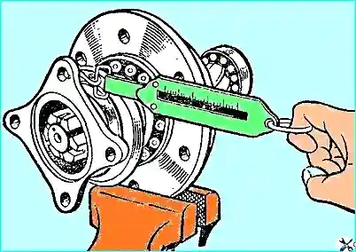
The bearings are checked using a spring balance (Fig. 7).
To do this, clamp the coupling in a vice, hook the spring balance onto the flange hole and smoothly rotate the pinion shaft.
The reading on the spring balance scale should be within 1.25-2.9 kg (which corresponds to a rotation moment of 6-14 kgm).
In this case, the initial force required to bring the coupling into rotation, is not taken into account.
If the bearing resistance to rotation is within normal limits, then the position of the nut relative to the tailstock should be noted, making marks on the end of the shaft and the nut.
After this, unscrew the nut, put the gland with the cover in place and tighten the nut to the position marked with a punch, and secure with a cotter pin.
Put the coupling in place, while to ensure normal operation of the gland, the stamped gland cover assembly should be centered on the flange neck. In this position, tighten the cover evenly with bolts.
If no other adjustments are required, assemble the main gear. When e Tighten the differential bearing nuts to the position indicated by the marks.
Put the main gear in place and connect the flanges of the cardan fork and the drive pinion shaft.
Adjusting the tightening of the differential bearings, side clearance and contact in the engagement of the main gear gears
The differential bearings and the engagement of the main gear gears are adjusted with the adjusting nuts as follows.
Engage the drive and driven gears with a small lateral clearance.
Tighten the adjusting nuts until they touch the outer rings of the differential bearings.
Alternately tighten the bearing nuts until some clearance appears between the teeth of the driven and drive gears and some preliminary tightening of the bearings is obtained.
When When tightening the bearings, turn the driven gear several turns in both directions to ensure that the bearing rollers are in the correct position.
Loosen the bearing adjusting nuts until they are clear of the outer rings, then tighten them until they touch the rings.
Adjust the differential end play to zero without pre-tightening the differential bearings.
With zero play and zero pre-tightening of the bearings, tighten the adjusting nut of each bearing by one notch to ensure pre-tightening of the bearings.
Install the gear tooth backlash indicator as shown in Fig. 8.
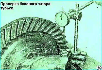
Check the clearance at four evenly spaced points.
To increase the lateral clearance, loosen the adjusting nut on the driven gear side and tighten the nut on the drive gear shaft side by the same number of notches to maintain the preliminary tightening of the bearings.
To reduce the lateral clearance, perform the above operations in the reverse order.
Finish turning the adjusting nuts tightening.
For example, if a nut needs to be loosened by one notch, then loosen it by two, and then tighten it by one notch.
This ensures that the nut touches the outer ring of the bearing and that the ring does not shift during operation.
The gap between the teeth should be 0.15-0.3 mm for different bridges, but it should not change by more than 0.1 mm in one bridge.
Checking the engagement with paint. After final assembly and adjustment, check the engagement of the gears.
For this purpose, paint the teeth with paint of the required viscosity. Very thin paint spreads and stains the surface of the teeth, too thick paint cannot be squeezed out of the spaces between the teeth.
Slow down the drive gear shaft and rotate the driven gear in both directions until a clear contact patch is visible
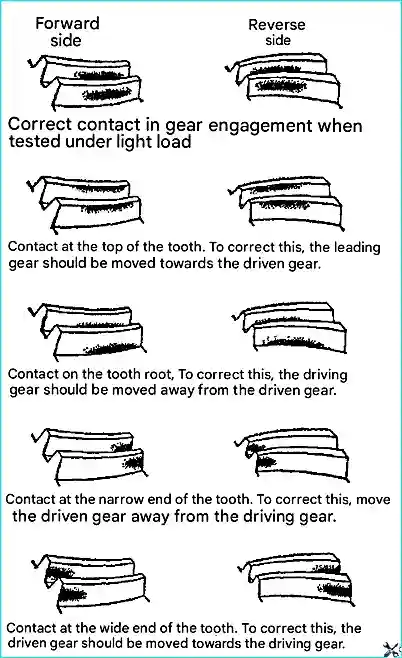
The correct contact patch of the teeth completes the check of the gear installation and the lateral clearance in the engagement.
The lateral clearance should be in the limits specified above. Fig. 9 shows typical contact patches on the teeth of the driven gear of the rear axle main transmission.
If during the adjustment it becomes necessary to move the drive gear shaft, this can be achieved by changing the thickness of the adjusting linings installed between the flange of the drive gear shaft bearing coupling and the end of the gearbox housing neck.
When the lateral clearance changes, the location of the contact patch changes.
To reduce the lateral clearance, the driven gear is moved toward the drive gear. In this case, the contact patch on the working (convex) side of the tooth moves slightly lower and closer to the narrow end of the tooth.
To increase the lateral clearance, the driven gear is moved away from the drive gear. In this case:
- - on the working side of the tooth, the contact spot moves slightly higher and closer to the wide end of the tooth;
- - on the non-working side of the tooth, the contact spot moves slightly higher and closer to the wide end.
When the driving gear moves toward the driven gear:
- - the contact spot on the working side moves lower and closer to the narrow end of the tooth;
- - the contact spot on the non-working side moves lower and closer to the wide end of the tooth.
When the driving gear moves away from the driven gear:
- - the contact spot on the working side of the tooth moves toward the top of the tooth and its wide end;
- - on the non-working side of the tooth, the contact spot moves toward the top of the tooth and moves slightly toward its narrow end. the end.
")

")
")
")
")
")
")
")