The front axle structure is shown in Fig. 1.
The main gear and differential of the rear and front drive axles are the same, with the exception of the oil intake device of the pinion shaft bearings, which is not used in the front axle.
A constant velocity cardan is used in the front axle.
The rectangular cross-section front axle housing consists of two halves stamped from sheet steel, welded along the horizontal axis of the axle.
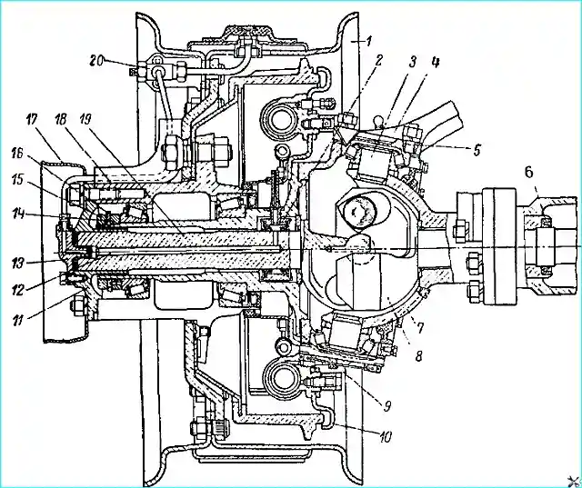
The middle part of the crankcase is offset relative to the longitudinal axis of the car to the left, flanges are butt-welded to the ends, to which the ball joints of the steering knuckles are attached.
Front axle maintenance
Front axle maintenance during operation consists of maintaining the required oil level in the crankcase and periodically changing it, lubricating the constant velocity cardan and kingpins, periodically checking the tightening condition of the kingpin bearings, checking the toe-in, tightening loose connections, checking the tightening condition of the pinion shaft bearings.
The engagement is adjusted only when installing new gears.
Malfunctions, their causes and methods of elimination in the main gear and differential of the front axle and rear axle are similar.
Repair of the front bridge
Removing the front axle from the vehicle. To remove the front axle, you must:
disconnect the flexible hose from the brake hydraulic lines on the left longitudinal beam. Unscrew the flexible hose from the front axle.
For the GAZ-66-01 vehicle additionally:
- - disconnect the hose from the tire pressure regulation system pipeline on the right longitudinal beam, unscrew the flexible air supply hose from the front axle;
- - disconnect the shock absorbers from the front axle;
- - disconnect the pipelines and flexible hoses from the power steering control valve, from the longitudinal steering rod, from the front axle and from the power steering cylinder;
- - disconnect the front propeller shaft from the flange of the front axle pinion shaft;
- - disconnect the longitudinal rod from the steering knuckle;
- - remove the linings, U-bolts and linings of the front springs;
- - roll back the front axle and install it on stand or supports.
Disassembling the front axle
Disconnect the longitudinal steering rod from the steering knuckle lever.
Remove the footrests. For the GAZ-66-01 vehicle additionally:
- disconnect the air supply line to the air valve from the front axle hub flange cover and from the valve.
Remove the protective cover, wheels, brake drum and protective cap of the shut-off clutch.
Using a special key, unscrew the bolt of the drive flange clutch, remove the clutch (while making sure that the stopper with the spring does not fall out of the hole in the cardan half-shaft).
Remove the drive flange (when removing the flange, do not unscrew the studs). For GAZ-66-01, additionally remove the hub flange cover.
Remove the hub with bearings.
Disconnect the brake hydraulic lines from the brake disc.
For GAZ-66-01, additionally disconnect the flexible air supply hoses to the sealing unit that pass through the brake discs.
Remove the brake shield with the oil deflector and the journal.
For GAZ-66-01, additionally remove the hub seal and unscrew the flexible air supply hose to the sealing unit from the sealing unit.
Remove the constant velocity cardans.
Press off the ball joint using the dismantling bolts. Remove the lever on the left steering knuckle housing and the set of adjusting shims.
Remove the upper kingpin pad of the right steering knuckle with the set of adjusting shims.
Remove the lower kingpin pads with the set of adjusting shims.
Remove the ball joint oil seal.
Remove the outer bearing races of the kingpins.
Remove the bearings from the ball joint kingpins.
Disconnect the ball joint and the steering knuckle housing.
Front axle malfunctions and how to fix them
Causes of malfunction - how to fix them
Violation of the correct camber angle of the wheels, the appearance of "wobbling" of the front wheels when driving and uneven tire wear due to large clearance in the front wheel hub bearings - Adjust the tension of the front wheel hub bearings
The car does not “hold” the road well due to a deflection of the front axle housing - Straighten the housing or replace the axle housing with a new one
Grease leaking through the rubber-felt seal of the steering knuckle due to its wear - Replace the seal
Increased tire wear due to incorrect wheel alignment (bent rod or incorrect setting of its length) - Straighten the rod or adjust its length
Disassembling constant velocity cardans
If necessary, the constant velocity cardan is disassembled in the following order.
Mark the relative positions of the cardan forks with paint or chalk.
Put cardan shaft in a vertical position with the short (driven) fork upwards so that the pin of the central ball can lower itself into the hole in the central ball under the action of its own weight.
If the pin does not lower, then knock the end of the long fork on a wooden stand or move the forks apart and lower the pin using a screwdriver.
Turn the central ball together with the pin and remove the pin.
Turn the central ball with the chamfer towards one of the driving balls, bend the driven fork, while one of the driving balls, which is opposite the chamfer, can be removed from the cardan shaft.
The remaining balls, after the first one is removed, are removed freely.
The requirements for the technical condition and permissible wear of the parts of the front and rear axles are similar.
Assembly of the front bridge
Assembling constant velocity cardans. Cardans are assembled after selecting new larger repair balls or as a result of replacing one of the forks.
The assembly procedure is as follows.
Clamp the leading (long) fork in a vice in a vertical position (with the fork facing up).
Install the central ball (without the pin) in the spherical recess of the leading fork with the chamfer to the side.
Place the driven fork on the central ball.
Turning the fork to the side, install three leading balls in the fork grooves one by one.
Having spread the cardan forks to the maximum angle and turned the central ball with the chamfer towards the groove of the fourth leading ball, insert this ball into the groove so that it passes by chamfers.
With the forks apart, insert the pin into the hole in the central ball.
Turn the central ball so that the axis of the central ball pin coincides with the hole in the driven fork. Move the forks so that the end of the pin enters the fork hole
The longitudinal movements of the constant velocity cardan in the bridge are limited by thrust washers, one of which is installed in the ball joint, and the other in the journal.
The preload in the cardan balls should be such that the moment required to rotate the fork by 10 - 15˚ in all directions from the vertical with the other fork clamped in a vice is equal to 500-800 kgf cm.
To ensure correct assembly and obtain the required preload, the driving balls are sorted into nine groups by diameter size (mm):
- Group 1 - 40.09 - 40.07
- Group 2 - 40.07 - 40.05
- 8th - 40.05 - 40.03
- 4th - 40.03 - 40.01
- 5th - 40.01 - 39.99
- 6th - 39.99 - 39.97
- 7th - 39.97 - 39.95
- 8th - 39.95 - 39.93
- 9th - 39.93 - 39.91
Diameter of the mounting ball, mm 34.85 ± 0.025.
Each cardan is assembled with balls of one group or two adjacent groups. For example, two balls with a diameter of 39.98 mm and two with a diameter of 40.00 mm.
During installation, balls of the same size must be positioned diametrically opposite each other.
The difference in diameters of two pairs of balls of one cardan shaft is allowed to be no more than 004 mm.
The cardan shaft is run-in on a stand at a changing fork angle from 0 to 30° for 2-3 minutes at 150 rpm.
During running-in, the cardan shaft is lubricated with oil.
The front axle is assembled in the reverse order of disassembly. When assembling, consider the following:
Press the bushing into the ball joint of the steering knuckle flush with the end face of the socket under the thrust washer.
For GAZ-66-01 vehicles, screw a flexible hose into the seal block before installing the steering knuckle.
When assembling and installing the steering knuckle seal, soak the felt outer ring in warm engine oil.
When installing the ball joint in a constant velocity cardan, apply consistent grease according to the lubrication chart.
Lubricate the kingpin bearings through grease nipples with grease according to the lubrication chart.
After assembly, the front axle is tested on a stand without a load and with a load. A properly assembled front axle must meet the following requirements.
There should be no increased noise or increased heating during operation of the axle.
There should be no oil leakage through the seal, covers and bolted connections.
Nuts shp Tighten the drive flange fastening bolt to the hub (torque 12-14 kgm).
Front axle adjustment
The bearings of the drive pinion shaft, differential, hub and the engagement of the main gear gears in the front axle are adjusted in the same way as in the rear.
Adjusting the tightening of the kingpin bearings.
Before checking the tightening of the kingpin bearings, check the tightening of the wheel hub bearings. The tightness of the kingpin bearings is checked with the wheels jacked up and the steering rods removed.
When checking, rock the wheels by hand in a vertical plane in several positions within the angle of rotation of the wheel on the kingpin.
The kingpin bearings must be adjusted so that there is absolutely no play in them, otherwise the bearings will quickly be destroyed.
To adjust the kingpin bearings, use 0.10 and 0.15 mm shims.
Factory-adjusted bearings have the same number and the same thickness of shims both on top and bottom.
When adjusting the kingpin bearings, be sure to remove the same number of shims on top and bottom, otherwise the alignment of the steering knuckle parts will be disrupted.
With correctly adjusted bearings, the steering knuckle should rotate relative to the kingpins by hand with a small amount of force.
When checking with a dynamometer, the force applied to the steering rod pivot arm, at the ball pin location, with the ball joint seals removed, with the front axle raised on a jack, the steering rods removed and the constant velocity cardan shaft removed, should be equal to 2.25 - 3.75 kg with smooth movement of the dynamometer.
When adjusting the upper kingpin on the left side of the front axle, before removing the longitudinal steering rod arm, disconnect the flexible hoses of the brake system and the tire pressure regulation system.
Never unscrew its studs to remove the steering rod.
Checking Front Wheel Installation
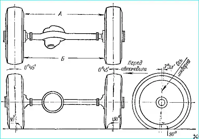
To ensure vehicle stability and prevent increased tire wear, the front wheel installation shown in the table is provided (Fig. 2).
front wheel alignment angles:
- - camber angle 0° 45’, forward angle of the lower ends of the kingpins 3˚ 30’;
- - toe-in 2 – 5 mm, lateral angle of the kingpins 9˚
Only toe-in is adjusted in a car. The angles of the kingpins and camber are not adjusted, but are provided by the design of the front axle.
During operation, these angles may be violated in the event of wear of parts, deflection of the casings from impacts in an accident or breakage of springs.
The camber angle of the wheels is the angle between the plane of the wheel and the vertical plane located parallel to the longitudinal axis of the car, it increases the stability of the car during movement.
This angle may be violated due to loosening of the bearings wheel hubs or deflection of axle shaft housings and ball joints.
The camber angle of the wheels is checked with instruments. If there are no devices, you can measure the dimensions between the vertical plane of the square and the lower or upper end of the wheel rim using a square.
The difference in dimensions corresponding to a given camber angle of 0˚45' should be equal to 4-9 mm.
To measure, place the vehicle with a full load on a horizontal surface with normal tire pressure and the wheels in a straight-ahead position.
Wheel toe-in is measured by the difference in the distances between the inner surfaces of the tires at the rear (B) (see Fig. 2) and at the front (A) approximately at the level of the wheel centers.
This difference, with the correct wheel toe-in, should be equal to 2-5 mm, i.e. B-A = 2-5 mm.
Wheel toe-in is adjusted by changing the length of the transverse steering rod. To do this, loosen the tightening of the end bolts and, squeezing the left or right tie rod pin out of the steering knuckle housing lever, rotate the end, achieving a toe-in of 2-5 mm.
To ensure adjustment within the specified limits, the ends have different thread pitches (left - 2 mm, right - 1.5 mm).
When adjusting the wheel toe-in, maintain the size of З63 ± 1 mm from the center of the ball pin of the right end to the end of the base of the mounting bracket of the power steering cylinder rod, since violation of this size will cause incorrect operation of the power cylinder.
After completing the adjustment, tighten the nuts of the end bolts until they stop, tighten the nut of the end pin and cotter pin.
When adjusting and finally tightening the end rods, ensure a gap (30 mm) between the rod and the bearing cover of the drive pinion shaft front axle.
This the gap is necessary to prevent the transverse tie rod from touching the axle gearbox housing when turning the wheels.
The wheel alignment is checked under the same conditions under which the camber angle is checked.
Used hub bearings
Front wheel hub bearings:
- - internal – 7515 (internal diameter 75, external diameter 130, width 33.5 mm);
- - external – 807813K1 (internal diameter 65, external diameter 110, width 30.5 mm).
")

")
")
")
")
")
")
")