The GAZ-53A and GAZ-66 vehicles are equipped with drum-type brakes with a hydraulic drive and a hydrovacuum booster
The front and rear brakes of the GAZ-53A are identical in design and differ only in size.
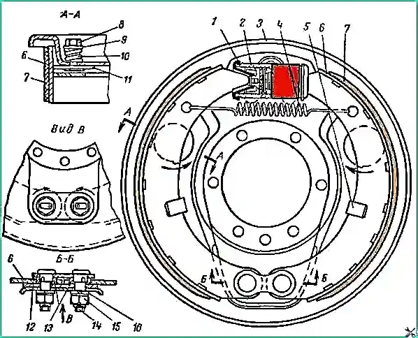
The rear brakes of the GAZ-b6, unlike the brakes of the GAZ-53A, do not have protective screens on the brake cylinders, but have rear shoes with long linings.
The front brakes of the GAZ-66 have two cylinders, each of which acts on its own shoe.
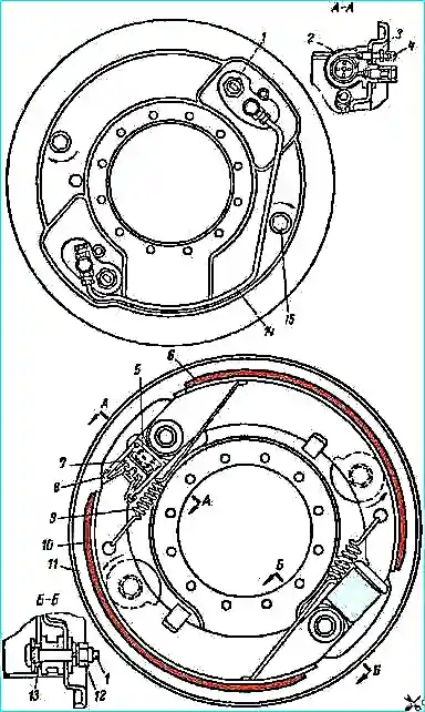
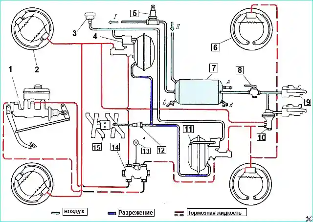
The design of the brakes is shown in Fig. 1 and 2. The operation of the hydraulic vacuum booster is based on the use of vacuum in the engine intake pipe.
The booster consists of a vacuum chamber, a vacuum control valve with a hydraulic drive and a hydraulic cylinder.
All these parts are combined into one hermetically sealed unit, which is mounted on two brackets on the longitudinal beam of the frame.
The vacuum chamber of the booster is connected to the engine intake pipe through a pipeline and a plate shut-off valve.
The shut-off valve is installed in close proximity to the vacuum source, due to which the maximum vacuum is maintained in the booster system.
Brake maintenance
Adjusting the gap between the pads and drums. The brakes should be adjusted when the brake drums have cooled down and the wheel bearings are correctly adjusted.
There are two brake adjustments: current and full
Current adjustment. As the brake friction linings wear, the gaps between the linings and the brake drums increase, and the pedal begins to approach the cabin floor when braking.
Current brake adjustment restores the original gaps between the friction linings of the shoes and the brake drums, compensating for lining wear.
To adjust the brakes, you must:
- - hang the wheel with a jack;
- - while rotating the wheel forward, slightly turn the shoe eccentric in the direction of the arrows shown in Fig. 1 and 2, until the shoe brakes the wheel;
- - gradually lower the eccentric, turning the wheel by hand in the same direction until the wheel rotates freely;
- - install the second shoe in the same way as the first, while rotating the wheel forward for the front brake of the GAZ-66 car and backward for the rear brake of the GAZ-66 car and all brakes of the GAZ-53A car.
After adjusting the clearance of the shoes, check the action of the brakes on the road.
Full adjustment. Full adjustment of the wheel brakes should be done when changing the friction linings, shoes or after mechanical processing of the drums.
When fully adjusting the brakes, it is necessary to:
- - hang the wheel with a jack;
- - slightly unscrew the nuts of the support pins and install the support the pad pins to their initial position;
- - pressing the brake pedal with a constant force of 12-16 kg, turn the support pins in the direction indicated by the arrows so that the lower part of the lining rests against the brake drum.
Torquet, when this occurs, is determined by the increase in resistance when rotating the support pin. Tighten the nuts of the support pins in this position;
- - turn the adjusting eccentrics so that the shoes rest against the brake drum;
- - release the brake pedal;
- - turn the adjusting eccentrics in the opposite direction so that the wheel rotates freely;
- - adjust the brakes of all wheels in this way.
After adjusting the clearance of the shoes of all brakes, check the action of the brakes on the road.
With correctly adjusted gaps between the linings of the shoes and drums, the brake pedal should drop no more than ⅔ of its full travel when fully braking.
If after adjustment, when the car is moving, the brake drums heat up slightly (the hand can easily tolerate touching the rim of the drum), then after several brakings the shoes will be worked in and the heating will stop.
If the drums are very hot, you need to find the shoes that are touching the drums and use adjusting eccentrics to move them away from the drums a little.
Adjusting the clearance between the pusher and the piston of the master cylinder
The clearance between the pusher and the piston of the master cylinder is necessary to prevent spontaneous braking of the car.
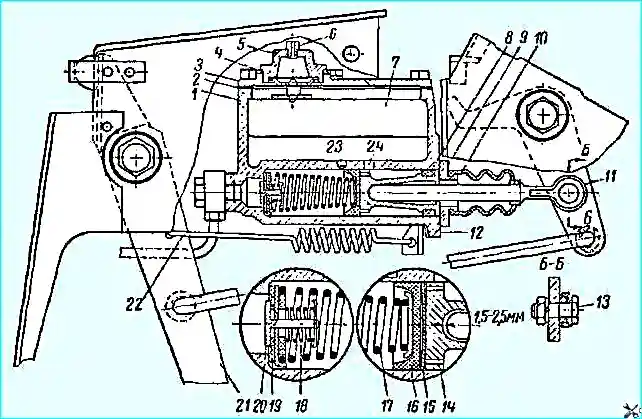
If the edge of the sealing cuff covers the compensation hole 23 (Fig. 3), the brakes will not be fully released, since some of the fluid cannot flow from the working part of the cylinder into the reservoir after braking is complete.
The gap should be 1.5-2.5 mm, which corresponds to 8-13 mm of free pedal travel, measured in the middle of the foot platform.
To measure the gap, you need to change the length of the pusher.
The procedure for adjusting the gap on a GAZ-53A vehicle is as follows:
- Disconnect the pedal and pusher, remove the cotter pin and remove the finger.
- Check the position occupied by the pedal under the action of the release spring.
- Pedal must rest against the rubber buffer secured under the inclined floor of the cabin.
- Twist (or unscrew) the pedal rod into the piston pusher so that the axis, when rolling in the piston of the master cylinder, is shifted back and does not reach the axis of the pedal hole by 1.5-2.5 mm. Without disturbing this position, securely lock the pedal connecting rod with a lock nut.
- Align the hole of the connecting rod and the pedal, insert the pin and cotter it. Check the amount of free play of the pedal.
The procedure for adjusting the gap on a GAZ-66 vehicle is as follows:
- Disconnect the intermediate lever and the pusher by removing the eccentric axis.
- Check the position occupied by the pedal under the action of the release spring. The pedal should rest against the bracket shelf with its rubber buffer.
- Install the master cylinder piston pusher until it stops against the piston in its extreme rear position.
- Connect the intermediate lever and the master cylinder piston pusher with an eccentric axis without changing their relative positions.
- Turn the eccentric axis in any direction at an angle to ensure a gap between the pusher and the piston equal to 1.5-2.5 mm.
- Install the washer and tighten the eccentric axis nut.
- Check the free travel of the brake pedal (8-13 mm).
Brake malfunctions and troubleshooting methods
Causes of malfunction (Methods elimination)
The brake pedal touches the floor of the cabin:
- Increased gaps between the brake drums and the friction linings of the shoes
Adjust the brakes using adjusting eccentrics
If the friction linings are badly worn (0.5 mm left to the rivet heads), replace them with new ones and perform a complete adjustment of the brakes
- Incorrect installation of the brake shoes
Perform a complete adjustment of the brakes
- Presence of air in the system
Bleed the system
- Fluid leakage in the pipeline system
Inspect the entire brake system and identify leak locations
If after tightening There is no leakage at the connection points stop, replace defective parts with new ones
- Fluid leaking from wheel cylinders or sealing cuffs of the hydraulic booster rod
Replace damaged cuffs, repair damage to cylinders or rod
- Insufficient fluid level in the master cylinder
Add the required amount of fluid
- Fluid leaking through the inner cuff of the master cylinder
Replace the inner cuff with a new one
The brakes do not release:
- No clearance between the pusher and the piston of the master cylinder
Adjust the free travel of the pedal
- Clogging of the compensation hole of the brake master cylinder
Clean the compensation hole hole with soft wire Ø 0.6 mm,
replace brake fluid if it is contaminated, flushing the entire system with alcohol
- Swelling of rubber seals due to mineral oil or any other petroleum-based liquid entering the system
Drain the brake fluid, disassemble all cylinders, flush their parts in alcohol
Flush the brake system
Replace brake seals
Before assembly, lubricate the cylinder parts with brake fluid
- Jamming of the piston of the hydraulic brake booster cylinder
Flush the system with alcohol and replace the fluid.
If the defect is not eliminated, remove the booster, check the condition of the working surfaces cylinder, piston and replace damaged parts if necessary
- Jamming of the brake booster control valve piston when returning to the lower position after stopping pressing the pedal
Remove the control valve, wash its piston and seals, as well as the hole in the cylinder with alcohol
Replace damaged seals or the spring if it does not provide a load of 2.5+0.5 kg when compressed to a height of 17 mm
One brake does not release:
- The brake shoe tension spring has weakened or broken
Replace the spring if, stretched to a length of 227 mm, it does not provide a load of 34-39 kg.
- The shoe rotates with difficulty on the support finger or jams in the guide bracket
Identify the cause of jamming and lubricate the sliding surfaces of the parts so that the lubricant does not get on the friction linings
- Piston jamming in the wheel cylinder due to corrosion or clogging
Disassemble the cylinder, wash the parts with alcohol.
If necessary, clean the cylinder surface with fine-grained sandpaper No. 100.
Before assembling the part, lubricate with brake fluid
When braking, the car pulls to the side:
- Oiling of the friction linings of one of the brakes or two brakes on one side
Wash the linings with gasoline and clean sandpaper
- - One of the brake shields or both shields on one side has come loose
- - Uneven tire pressure on left and right wheels
Tighten the shield(s) mounting bolts and adjust the gaps between the pads and drums, bring the tire pressure to normal
High pedal force due to a malfunction of the hydraulic vacuum booster or its system:
- Loose connections in the vacuum line
Eliminate loose connections in the line
- Clogged air filter of the booster
Wash the filter in gasoline, moisten with oil and put it back in place
- Torn chamber diaphragm amplifier
Disassemble the amplifier chamber and replace the diaphragm
")

")
")
")
")
")
")
")