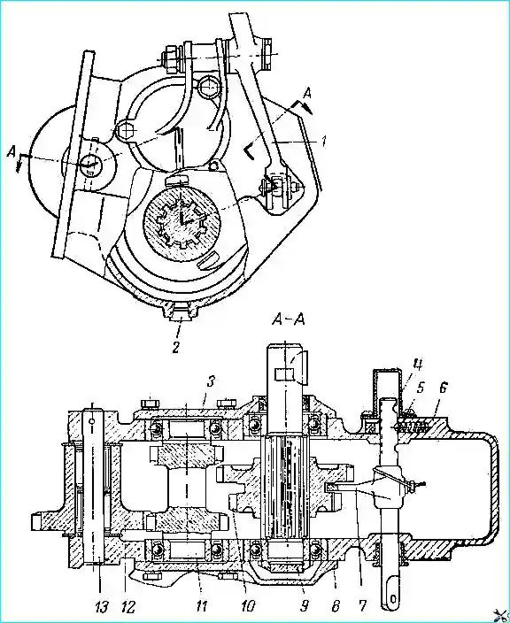
The power take-off device is shown in Fig. 1
The power take-off is secured with studs to the gearbox on the right side and serves to transmit power from the gearbox to the winch
It has two gears: for winding the cable onto the drum with a gear ratio (from the engine) of 2.41 and for unwinding the cable with a gear ratio (from the engine) of 1.7.
The power take-off is driven by the third gear pinion of the gearbox intermediate shaft, with which the drive pinion of the power take-off is in constant engagement.
The power take-off is controlled from the driver's seat with a lever.
The gears and bearings of the power take-off are lubricated with oil poured into the gearbox housing.
Power take-off box maintenance
Power take-off box maintenance during operation consists of checking the condition of the fasteners and periodically changing the lubricant.
When draining the lubricant from the gearbox, also unscrew the drain plug of the power take-off box.
Power take-off box malfunctions and how to fix them
The power take-off box consists of the same parts as the gearbox, so the malfunctions and methods of elimination will be similar to those of the gearbox.
However, some malfunctions in the power take-off box should be given special attention.
These include:
Excessive noise in the operation of new gears. The cause of this defect may be an incorrect center distance of the gearbox and power take-off box gears. power.
Therefore, when replacing the sealing gasket between the flange of the power take-off housing and the mating surface of the gearbox, it is necessary to ensure that the thickness of this gasket is equal to 0.7-0.9 mm.
The correct thickness of the specified gasket ensures the required center-to-center distance of the gearbox and power take-off gears and their normal engagement.
Self-disengagement of the driven shaft gear block. This malfunction may be a consequence of poor assembly of the unit, which did not ensure the required fit of the block on the splines of the driven shaft.
In this regard, when assembling the power take-off, the gear block should be carefully selected according to the shaft splines.
The selection should ensure the absence of noticeable angular movement of the block when it slides freely along the splines of the driven shaft.
After selection, the location of the splines shaft and block mark.
If oil leaks through the shift rod seal, tighten the seal nut a little.
Power take-off repair
Remove the power take-off from the vehicle together with the gearbox.
Disassemble the power take-off in the following order.
- 1. Disconnect the lower end of control lever 1 from rod 4 (see Fig. 1).
- 2. Remove the control lever axle and lever, press out the bushing from the lever hole
- 3. Press out the pin securing axle 13 of the drive gear, press out the axle, remove drive gear 12 and support washers, take out the drive gear bearings.
- 4. Remove the key from the driven shaft 9.
- 5. Remove the front cover 3 and gasket.
- 6. Press the driven shaft oil seal out of the cover.
- 7. Remove the rear cover 8 of the bearings.
- 8. Remove the intermediate shaft 11, press out the front and rear bearings of the intermediate shaft gear block.
- Punch and unscrew the driven shaft nut, remove the driven shaft and gear block, press out the rear and front bearings of the driven shaft.
- 9. Knock out the crankcase hatch plug.
- 10. Remove the plug of the hole for the lock.
- 11. Remove the protective cap of the rod.
- 12. Remove rod 4, fork 7, retainer, spring, unscrew the rod nut, remove the ring, washer and oil seal.
Assembly
Before assembly, lubricate all parts of the power take-off box with oil poured into the unit.
Before installing, lubricate the threaded part of the bolts with paint. When assembling, use only new gaskets and oil seals.
Assemble the power take-off box in the reverse order of disassembly, taking into account the following instructions.
Match the sliding block of gears according to the splines of the driven shaft.
The selection should ensure the absence of noticeable angular play when the block slides freely along the shaft.
The angular play on the splines should not exceed 0.08 mm when checking on the radius of the pitch circle of the ring gear with a number of teeth equal to 24.
Insert the sliding block of gears into the inner cavity of the crankcase so that the toothed ring with straight teeth is located on the side of the hole for the retainer, and the gear engagement fork enters the groove of the block of gears.
Install the rear bearings of the intermediate and driven shafts flush with the plane of the crankcase.
Press the inner rings of the ball bearings of the driven and intermediate shafts until they stop against the ends of the flanges on the shafts.
A 003 mm feeler gauge should not fit between the ends of the flanges and the rings.
Punch the driven shaft bearing fastening nut, screwed all the way in into the shaft groove.
After installing the rubber seal, metal washer and felt ring on the rod, tighten the seal nut until it rotates tightly.
Before installing, lubricate the working surface of the driven shaft seal.
Press the seal into the front cover flush with the outer end of the cover.
Put the plug into the crankcase groove with SK-OCB paste.
Press the rod plug into the hole for the locking ball flush with the crankcase wall.
Press the drive gear axle into the crankcase flush with the plane of the boss. Align the hole in the axle and the crankcase boss.
Before installing the axle, lubricate the holes in the crankcase with SK-OCB paste. Press the axle mounting pin flush with the end of the boss.
Press the bushing into the hole in the power take-off control lever until the end of the bushing rests against the outer end of the lever.
Place the assembled power take-off on a stand and test it without load for noise, oil leakage, and ease of shifting.
Fill the power take-off with spindle oil before testing.
")

")
")
")
")
")
")
")