The engine cooling system is liquid, closed with forced circulation
The direction of circulation is shown by arrows in the figure
The liquid circulates depending on the heating in two circles, in a small and large circle.
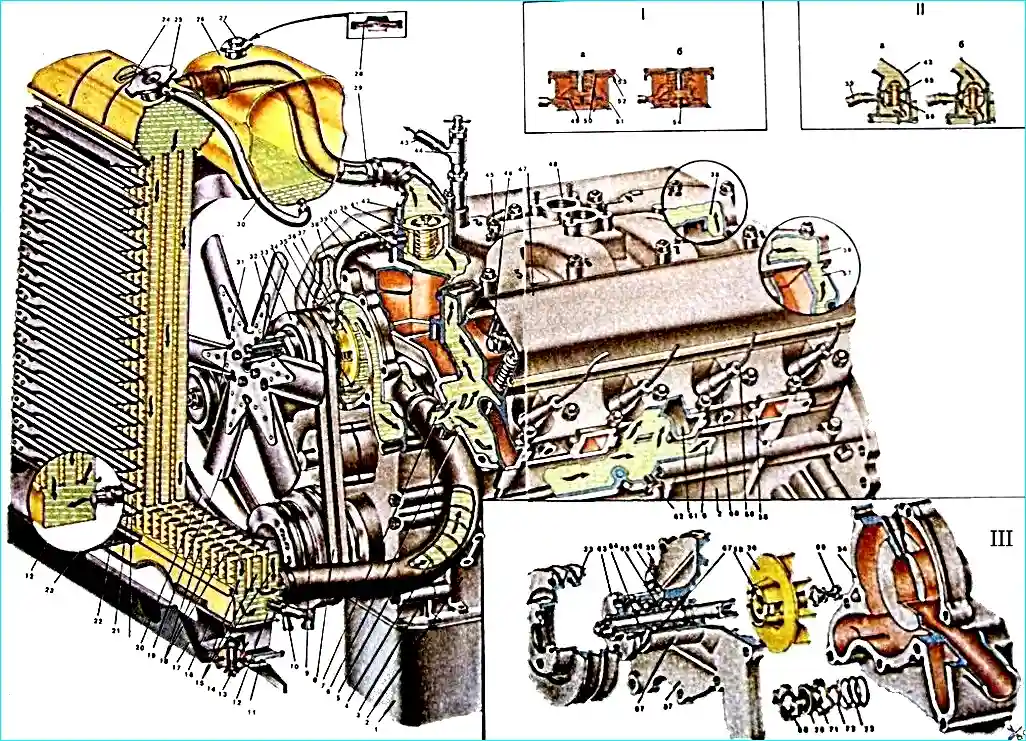
Cooling system engine:
(I) Radiator cap:
- - (a) The steam (bleed) valve of the radiator cap opens at an excess pressure in the system of 0.45–0.55 kgf/cm², which corresponds to a coolant temperature of 109–111°C.
- - (b) The air (inlet) valve opens at a vacuum in the system of 0.01–0.10 kgf/cm².
(II) Thermostat operation diagram:
- - (a) The thermostat valve is closed at a temperature below 78°C.
- - (b) The thermostat valve is fully open at a temperature above 91°C.
(III) Water pump and components of the cooling system:
- Engine oil sump. 2. Cylinder block. 3. Timing gear cover. 4. Expansion spring (hose frame). 5. Radiator outlet hose. 6. Cylinder block cooling jacket. 7. Channel for supplying coolant to the block. 8. Fan, water pump and generator drive belts. 9. Crankshaft pulley. 10. Radiator drain cock. 11. Radiator mounting bracket. 12. Lower radiator tank. 13. Radiator tank bracket. 14. Radiator suspension cushion. 15. Radiator pipe. 16. Lower radiator plate (reinforcer). 17. Front mudguard. 18. Radiator fins. 19. Fan. 20. Fan casing. 21. Radiator blind fins. 22. Lower louver plate. 23. Heater fluid drain hose. 24. Radiator fluid overheating indicator lamp sensor. 25. Radiator cap. 26. Expansion tank. 27. Expansion tank cap. 28. Expansion tank cap valve. 29. Radiator inlet pipe. 30. Connecting hose from radiator filler neck to expansion tank. 31. Generator. 32. Fan spacer ring. 33. Fan pulley. 34. Water pump socket in timing gear cover. 35. Water pump oiler. 36. Water pump impeller. 37. Water pump housing. 38. Inlet pipe cooling jacket. 39. Bypass hose of small coolant circulation circle. 40. Inlet pipe. 41. Thermostat. 42. Outlet pipe. 43. Hot water supply hose to the heater. 44. Heater shut-off valve. 45. Coolant temperature gauge sensor. 46. Valve rocker arm shaft. 47. Rocker arm covers. 48. Carburetor flange. 49. Outlet plug valve. 50. Plug cover spring. 51. Radiator filler neck. 52. Sealing gasket. 53. Plug cover housing. 54. Inlet plug valve. 55. Thermostat valve. 56. Thermostat sensor. 57. Cylinder head cooling jacket. 58. Cylinder head. 59. High tension wire. 60. Spark plug. 61. Cylinder head exhaust channel. 62. Starting heater supply pipe. 63. Fan pulley hub. 64. Roller water pump. 65. Expansion sleeve. 66. Control hole for grease outlet. 67. Water pump bearings. 68. Water pump sealing washer. 69. Impeller fastening bolt. 70. Oil seal cuff. 71. Wall seal. 72. Oil seal cuff ring. 73. Spring seal.
When the engine is cold, when the thermostat valve is closed, bypassing the radiator, through the bypass hose 6 into the suction cavity of the water pump, and then into the engine water jacket - this is a small circle.
When the engine is warm, when the thermostat valve is open - through the outlet pipe along the hose into the upper tank of the radiator, and from the radiator through the supply hose into the engine water jacket - this is a large circle.
Maintenance of the cooling system
Daily before leaving, check the coolant level.
The water level in the radiator should be 40 mm below the upper edge of the filler neck, the level of the antifreeze liquid is 70-80 mm.
Pour clean soft water into the radiator and change it as little as possible. In the spring (or better yet, twice a year), it is recommended to flush the cooling system.
Proper operation of the engine is the most reliable method of combating scale and corrosion in the cooling system. If scale has appeared, the radiator is flushed as follows.
The radiator is removed from the car, then a 10% solution of caustic soda (caustic soda), preheated to a temperature of 90˚ C, is poured into it.
After 30-40 minutes, the solution is drained and the radiator is flushed with clean running water in the direction opposite to normal circulation. If necessary, the flush is repeated.
To avoid destruction of the al It is unacceptable to pour alkali solution into the cooling jacket of the cylinder block of aluminum parts.
The caustic soda solution should be handled with care, as it causes skin burns and corrodes clothing fabrics.
The engine cooling jacket can be protected from corrosion as follows.
Prepare a solution of chromium picate at a rate of 4-8 g per 1 liter of water and pour it into the cooling system. Work with this solution for a month (best in the summer), and then drain it.
If water boils out of the solution during operation, add water to the system, and if there is a leak, add the solution.
You should know that a solution of chrompic less than 3 g per 1 l leads to increased corrosion of aluminum parts.
The drive belts of the units installed on the engines must be tensioned so that they do not slip on the drive pulleys and there are no large loads on the bearings of the units due to overtensioning of the belts.
The tension of the water pump and fan drive belt on the GAZ-53A engine must be such that under a force of 4 kgf applied in the middle of the tension roller - water pump pulley branch, the deflection arrow does not exceed 10-15 mm, and in the middle of the water pump pulley branch pump - generator pulley 10-12 mm.
The tension of the water pump belt is adjusted by moving the tension roller, and the generator drive belt is adjusted by moving the generator itself.
On the GAZ-66 engine, the water pump drive belt is also the generator drive belt. Its tension is adjusted by moving the generator.
The deflection of the generator - water pump branch under a force of 4 kgf should not exceed 10-15 mm.
The tension of the compressor drive belt and the power steering pump is adjusted by moving the power steering pump.
The deflection of each of the two belts should be no more than 15-20 mm under a force of 1 kgf on the compressor pulley -► power steering pump pulley branch.
During major repairs of the radiator the upper and lower cans must be removed from it.
The outer surface of the radiator must be cleaned of dirt, and the inner surface of the tanks and tubes - from scale.
Dents on the walls of the tanks must be straightened.
The radiator tubes must be checked with a special rod made according to the size and profile of the tubes.
Covered and dented tubes must be replaced with new ones.
It is permissible to plug no more than 10 tubes and replace no more than 50 tubes.
After repair, the tubes must be blown out with compressed air.
The cooling plates must be straightened.
The assembled radiator must be thoroughly washed with an alkaline solution to neutralize zinc chloride and with water to remove the alkali.
The repaired radiator must be tested for leaks with compressed air under a pressure of 1 kg/cm 2.
A radiator filled with compressed air and immersed in water must not leak air.
The radiator cap must be airtight. The plug bleed valve must open under an air pressure of at least 0.45-0.55 kg/cm 2. The inlet valve should open at a vacuum of 0.01-0.10 kg/cm 2.
Bent radiator shutter plates should be straightened or replaced with new ones.
Repaired shutters should open and close freely when turning the lever within 90°.
When closing the shutters, the gaps between the surfaces of the plates should not exceed 1.5 mm over a length of 200 mm.
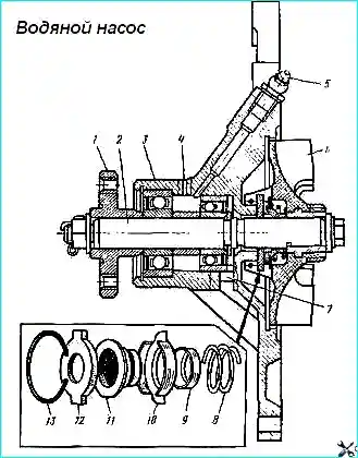
The water pump is centrifugal type.
A self-tightening gland with a spring serves to seal the pump. The rubber cuff of the gland and the graphite-lead washer rotate together with the shaft 2 (Fig. 2).
Fluid leakage through the inspection hole 7 indicates a malfunction of the gland. In this case, the pump should be repaired.
To replace the seal parts, the impeller of the pump must be removed, having first unscrewed the bolt.
It is not allowed to plug the inspection hole 7, since in this case the liquid leaking from the pump gets into the bearings and damages them.
The bearings are lubricated through the oiler 5 until fresh grease appears from the inspection hole 4. Excess grease must be removed.
Before assembling the water pump, all parts must be wiped and blown with compressed air.
When installing the impeller and the seal of the water pump in the housing, the end surfaces of the textolite sealing washer must bebe coated with a thin layer of graphite colloidal grease.
Bearings must be lubricated with refractory grease TSIA-TIM-201.
Fill bearings with grease until it appears in the inspection hole of the housing. Fill the hub cover with TSIA-TIM-203 grease when installing.
When the water pump shaft rotates, the impeller should not touch the housing, the water pump seal should be tight.
Check the water pump for leaks on a special stand at 3250 rpm and a water temperature of at least 40°C.
GAZ-53 Tension Roller Before assembly, all parts of the tension roller must be washed and wiped.
During assembly, squeeze the retaining ring on the tension roller axle in the annular groove of the axle to a size of 21.5 mm along the outer diameter of the ring no more.
Put 4-5 g of TSIA-TIM-201 grease into the bearing cavity.
")

")
")
")
")
")
")
")