The generator works in conjunction with the relay regulator PP-130 on GAZ-53A and GAZ-66 cars and with the relay regulator PP-111 on a shielded car
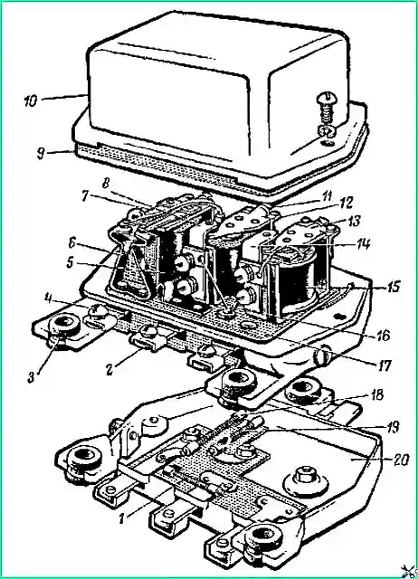
The relay regulator consists of three devices: a reverse current relay, a voltage regulator and a current limiter. A general view of the PP130 relay regulator is shown in Fig. 1.
The relay-regulator has three clamps, and the relay-regulator PP 111 has four plug connectors for connecting wires.
Relay-regulator PP 111 has an additional terminal “K” for connecting a discharge indicator lamp.
Inside the relay-regulator, terminal “K” is connected to the yoke of the reverse current relay.
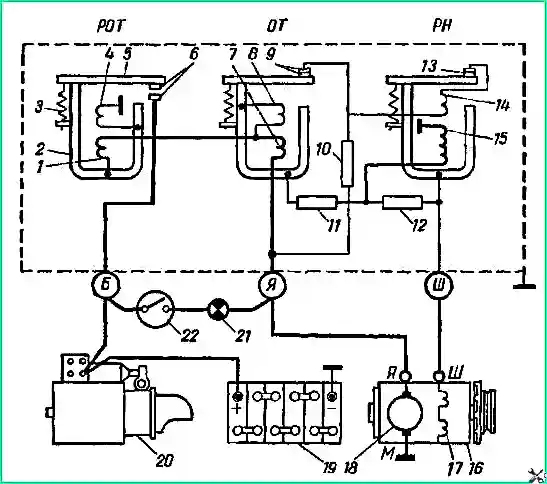
The electrical circuit of the relay-regulator PP-130 in connection with the generator and battery is shown in Fig. 2.
Relay-regulator maintenance
Checking the adjustment of the relay regulator on a car
To check, have a DC voltmeter with a scale of 20-30 V and a division value of 0.1-0.2 V. as well as a direct current ammeter with a scale of 30 amperes (preferably with a double-sided scale with a zero in the middle) and a division value of 1 ampere or the NIIAT E-5 device.
Checking the reverse current relay
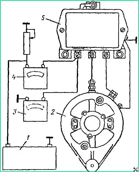
Disconnect the wire from terminal “B” of the relay-regulator and connect ammeter 4 between the end of this wire and terminal “B” (Fig. 3).
Connect voltmeter 3 between terminal “I” of the relay regulator and ground.
Start the engine and, slowly increasing the speed, use the deflection of the ammeter needle to determine the voltage at which the relay contacts close.
The voltage should be within 12.2-13.2* volts, and when operating the car in the southern regions, the adjustment should be within 11.5-12.5 volts.
Reducing the engine crankshaft speed, use an ammeter to determine the reverse current strength at the moment the relay contacts open.
The reverse current strength should be in the range of 0.5-6 amperes.
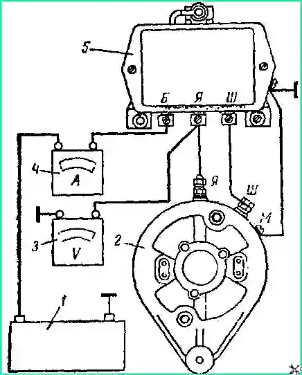
Checking the current limiter. Switch on the measuring instruments as shown in Fig. 4.
Start the engine and increase the crankshaft speed to 1600-2000 rpm, which corresponds to the vehicle moving in direct gear at a speed of 40-50 km/h.
Turn on all current consumers and use a rheostat to increase the load on the generator, observing the ammeter needle.
With a further increase in load, a moment comes when, despite the increase in load, the ammeter needle becomes.
The maximum ammeter reading will correspond to the current limiter adjustment. The strength of the limited current should be in the range of 26.5-29.5 amperes.
When checking the current limiter, take the ammeter reading quickly. Otherwise, 1-2 minutes after starting the engine, the charging current will become less than the value indicated above.
So that you can use the speedometer when checking the current limiter, jack up the rear axle and place it on stands, and place stops under the front wheels.
Checking the voltage regulator
While the engine is running, the battery must be disconnected. Connect voltmeter 3 to terminal “B” of the relay regulator according to Fig. 4.
At 1600-2000 rpm of the crankshaft, the voltmeter should show no more than 15.5 volts.
If the voltage is above 15.5 volts, then adjust the regulator.
If the voltage does not exceed the specified value, turn on such a number of consumers that the generator load corresponds to 14 amperes.
The voltmeter reading should be 13.8 - 14.8 volts, and if the car is operated in the southern regions, the adjustment should be within 13.2-14 volts.
Relay-regulator malfunctions and ways to eliminate them
- Cause of malfunction
Remedy
No battery charge:
- burning of the contacts of the voltage regulator or current limiter.
Clean the contacts and check the adjustment of the relay regulator
- Broken shunt winding of the reverse current relay
Repair the break or replace the coil
- The voltage regulator adjustment is broken
Adjust the voltage regulator
Battery overcharged or undercharged:
- The voltage regulator adjustment is broken
Adjust the relay-regulator
- Sintering of voltage regulator contacts
Replace contact system
Sintering of reverse current relay contacts:
- Installing a generator with a different polarity
Replace contact system
Remagnetize the generator by connecting terminal “Ш” to the plus terminal of the battery and the generator housing to the minus terminal for 2-3 seconds
Repair and adjustment of the relay regulator
In addition to the instruments that are used to test the relay regulator on a car, the workshop must have a test bench equipped with an electric motor that allows you to smoothly change the speed of the generator armature to at least 3000 rpm, a battery, a rheostat (lamp or wire ), allowing you to create a load of up to 30 amperes in the generator circuit.
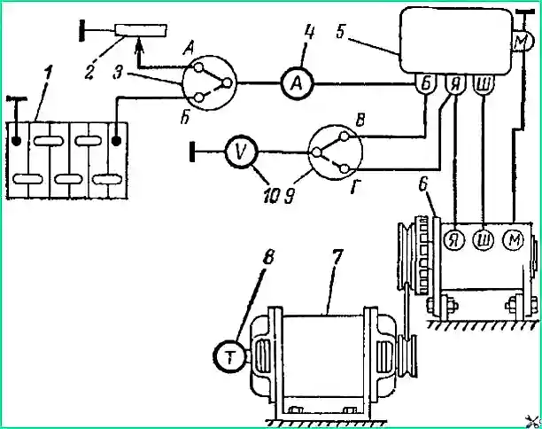
The diagram of the simplest stand for testing the relay regulator is shown in Fig. 5.
If the relay regulator is faulty, remove the cover and carefully inspect it.
You need to check:
- whether the relay-regulator is dirty as a result of damage to the sealing gasket and whether water is penetrating under the cover.
If necessary, clean the parts from corrosion and dirt and replace the sealing gasket;
- whether there are unreliable electrical connections, mechanical damage to parts or damage to the insulation of the coils due to overheating.
Eliminate any faults noticed and replace damaged parts;
- are there any signs of burnt or dirty contacts.
High contact resistance of the contacts, resulting from their burning or contamination, as well as weakening of the spring tension are most often the reasons for the violation of the normal adjustment of the relay regulator.
In these cases, to restore normal operation of the relay regulator, it is enough to clean the contacts and adjust each of the devices.
You need to clean the contacts with a needle file or glass sandpaper with a grit of 170.
After cleaning, you need to remove dust and small particles of carbon deposits by placing a piece of clean, dry suede or lint-free cloth soaked in alcohol between the contacts.
It is prohibited to use emery cloth to clean contacts;
- - are the resistances in good working order and are they fastened securely? Replace faulty resistances;
- - are the nuts securing the coil cores to the base tightly tightened;
- - are the gaps between the contacts and between the armatures and cores of the voltage regulator and current limiter normal? If necessary, adjust the gaps.
When measuring the gaps between the armature and the When making a core, keep in mind that the gap must be measured from the armature to the core, and not to the brass rivet, which is designed to protect the armature from “sticking” to the core when being pulled.
Adjusting the gaps of the relay regulator
For a reverse current relay (ROT), the gap “A” (Fig. 6) between the armature 4 and the diamagnetic washer of the core 3 should be 0.6-0.8 mm when the contacts are open and at the moment the contacts are closed 0.2-0 .3 mm.
The gap “B” between the contacts must be at least 0.25 mm.
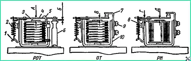
The gap between the armature and the diamagnetic washer is changed by bending the armature stroke limiter 5.
The gap between the contacts is changed by bending the stand of the lower contacts.
For a voltage regulator (RN) and a current limiter (OT), the gaps “V” and “D” between the armature and the core with closed contacts should be in the range of 1.35-1.55 mm.
To adjust the indicated gaps, loosen the screws securing the upper contact post and move it to set the required gap.
The gap “G” at the voltage regulator between the earring and the armature should be 0.2-0.35 mm.
After assembling and adjusting the gaps, check the relay-regulator and adjust if necessary.
Adjusting the reverse current relay. Install the relay regulator on the stand and connect it according to the diagram shown in Fig. 5.
Switch 3 to position “B”, and switch 9 to position “G”.
Turn on the electric motor and, slowly increasing the speed of the generator armature, notice at what voltage the reverse current relay turns on.
The moment of switching on is determined by the deflection of the ammeter needle.
If the switching voltage of the reverse current relay does not correspond to the required value, then adjust it by tensioning the spring and bending the spring post.
After adjusting the reverse current relay, check it several times, for which, by reducing the speed of the generator armature, use an ammeter to note the current strength at which the relay contacts open.
Adjusting the voltage regulator
To adjust, switch switch 3 (see Fig. 5) to position “A”, and switch 9 to position “B”.
Increase the generator armature speed to 3000 rpm.
Rheostat 2 creates a load of 14 amperes.
If the adjustable voltage does not correspond to the required values, then it must be adjusted by spring tension.
Adjusting the current limiter
The switching on of devices and the generator armature speed remain the same as when checking the voltage regulator.
The rheostat creates a load of 28 amperes, observing with an ammeter, after which value the current stops increasing with a further decrease in the resistance of the rheostat.
The current should be between 26.5 and 29.5 amperes.
The amount of limited current is regulated by spring tension, similar to a voltage regulator.
After adjustment, put the cover on the relay-regulator and recheck all devices.
")

")
")
")
")
")
")
")