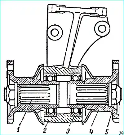
The winch device is shown in Fig. 1.
To increase the efficiency, the winch uses a globoidal transmission
The winch gearbox consists of a cast iron hub and a bronze crown welded to it.
To prevent overloading of the winch parts, its worm is connected to the winch drive cardan shaft using a safety pin.
The winch is equipped with an automatic brake mounted on the worm.
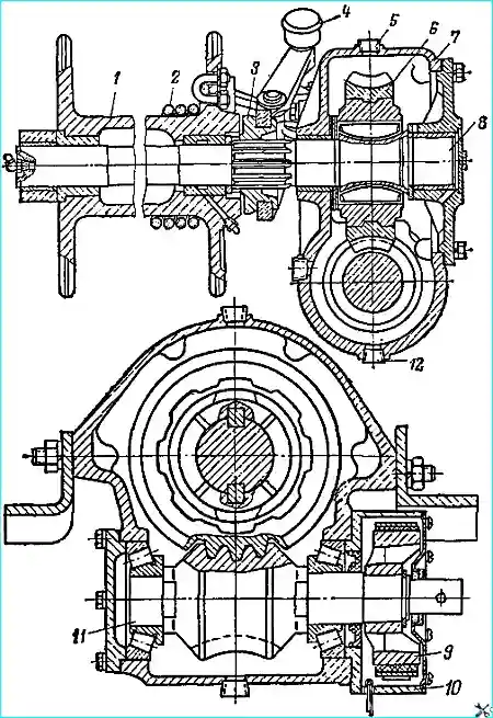
The winch control fork is equipped with a retarder brake that slows the drum when the cable is unwound by hand.
The length of the cable is 50 m. The maximum force applied to the cable is 3500 kg.
Winch maintenance
Winch maintenance consists of periodic lubrication of the cable guide rollers, the splines of the winch drum shaft and the drum engagement clutch, the winch drive cardans, the drum bushings, cleaning the winch and its drive from dirt.
Periodically check the oil level in the gearbox housing and top it up if necessary, and also check if there is oil (or water) in the automatic brake housing, if so, drain it through the drain hole at the bottom of the housing, closed cotter pin.
Wipe the cable as needed and lubricate it with liquid oil.
Monitor the tightening condition of the worm and worm gear bearings.
If there is slight play in the bearings or the worm gear tightens, adjust them as indicated below.
Adjust the automatic winch brake as needed by tightening the brake band with the nuts installed on its long end (above the spring).
Adjust the brake so that when the winch is operating with the drum clutch disengaged for 1-3 minutes, the brake housing does not heat up above the temperature that the hand can withstand.
The winch drum retarder is adjusted by changing the degree of spring tension using the nuts installed on the shoe bolt brakes.
The retarder is adjusted so that when the cable is wound manually (the cam clutch is disengaged), the drum cannot rotate at a speed greater than the speed of cable winding, i.e. so that the cable on the drum does not weaken.
The stop of the drum engagement fork, located on the upper shelf of the buffer, is secured so that when the fork is engaged, there is a gap of about 1 mm between its stopper and the stop.
Winch malfunctions and how to eliminate them
- Causes of malfunction
Ways to eliminate
The safety pin is cut off at low loads on the cable:
- high friction in the globoidal transmission and excessive wear of the worm gear due to long-term operation without breaks
Replace the worn one gear
- The oil in the gearbox heats up to a high temperature and loses its properties
Drain the oil and add new
The winch drum does not rotate when the winch drive cardan shaft rotates:
- The drum is not turned on
Set the fork to the on position
The safety pin is cut off
Immediately press the clutch pedal and turn off the power take-off box.
Replace the cut pin with a new one.
When replacing worn winch parts, it is necessary to ensure the required clearance in the fit of the cardan fork on the worm shaft.
This clearance should be within 0.12-0.18 mm.
When using the winch, uneven (one-sided) winding of the cable on the drum:
- Deviation of the cable from the direction perpendicular to the drum axis
Use the winch block
- One of the winch cable side guide rollers does not rotate
Lubricate or replace the roller
Automatic brake does not work:
- Incorrect brake adjustment
Adjust the winch brake
- Severe wear of the brake band
Replace the brake band
- Oiling of the brake band due to grease leakage through the brake housing oil seal
Replace the oil seal
Seizure of the metal-ceramic bushings of the winch drum:
- There is no required clearance in the connection of the shaft with the bushings
Install clearances within the range: 0.025-0.085 mm for the crankcase and crankcase cover bushings and 0.1-0.175 mm for the crosshead bushing
Scuffing of the shaft surfaces on which the drum bushings operate:
- Foreign particles getting onto the rubbing surfaces
Remove foreign particles
- The required clearance in the fit of the bushings on the shaft is not ensured
Set the clearance to within 0.75-0.165 mm
- Long-term operation of the winch with the drum disconnected
Do not allow the winch to operate with the drum disconnected
Winch repair
The winch must be disassembled in the following order.
- 1. Unwind the winch cable 2 (see Fig. 1) and remove the cable stirrup and crossbar.
- 2. Remove the elbows.
- 3. Remove the winch drum 1 and unscrew the grease nipple from it. Remove the winch engagement fork shaft; remove the retarder shoe, fork, shoe bolt, its washer and spring.
- 4. Remove the shaft thrust ring and cam clutch 3.
- 5. Remove the cover of the 10 brake housing, take out the brake band and spring.
- 6. Remove the retaining ring and the drum of the automatic brake 9.
- 7. Remove the brake housing and adjusting linings.
- 8. Remove the worm bearing cover, the gearbox housing cover and linings.
- 9. Press the outer rings of the worm bearings out of the housing. Do not allow the bearings to come apart when disassembling the winch.
- 10. Move the winch drum shaft and turn the worm 11 to remove the latter from the housing together with the inner rings of the bearings.
- 11. Remove the winch drum shaft together with the worm gear, spacer washers and adjusting ring.
- 12. Remove the adjusting ring, large and small spacer washers from the drum shaft, press the worm gear off the shaft and knock out the keys.
- 13. Press the inner bearing rings off the worm.
- 14. Press out the oil seal and remove the cotter pin from the brake housing drain hole.
- 15. Press out the brake housing cover sealing ring.
- 16. Press out the plug and remove the gearbox housing cover gasket.
- 17. Unscrew the winch cable coupling nuts, separate the coupling halves and release the cable.
Determining the technical condition. General requirements for the technical condition of winch parts are similar to the requirements for the condition of gearbox parts.
It should be borne in mind that the final processing of replaced crankcase bushings, crankcase covers and crossbars should only be done after they have been pressed in.
Worm. In case of bronze dragging on the worm thread, remove the bronze layer with fine sandpaper.
The worm with the worm wheel must not be disassembled.
Automatic brake band with friction linings in assembly.
Friction linings may wear to a size from their working surfaces to the rivet heads of at least 1 mm.
Drum brake shoe in assembly.
Friction lining may wear to a size from its working surface to the rivet head of at least 0.5 mm.
If the friction lining is oiled, wipe it with gasoline.
Assembly
Assemble the winch in the reverse order of disassembly, taking into account the following instructions.
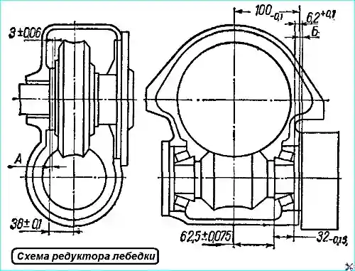
Before assembly, measure the actual deviations (with their signs) of the following dimensions of the winch parts (Fig. 2):
- - size 100 mm from the axis of the gearbox housing opening for installing the gear to the end face of the brake housing mount;
- - size 38 mm from the axis of the gearbox housing openings for installing the worm to the inner support end face of the housing;
- - height of the support shoulder of the brake housing 6.2 mm;
- - height of the worm bearing 32 mm;
- - size 62.5 mm from the globoid axis to the support end face of the bearing of the long end of the worm;
- - thickness of the large spacer washer 3 mm.
Calculate the thickness of the adjusting ring for installing the worm gear. To do this, add the actual dimensional deviations to the 2 mm size (nominal thickness):
Grind the adjusting ring to the calculated size.
Calculation example. Actual deviations were:
- ‑ Size 38 mm - +0.10 (grind the ring to size A = 2 + 0.10 - 0.05 = 2.05 ± 0.01 mm)
- ‑ Size 3 mm - +0.05.
Determine the thickness of the worm installation adjusting lining pack in the axial direction. To do this, add the actual dimensional deviations to the size of 0.7 mm (nominal thickness):
- - 100 mm (crankcase);
- - 6.2 mm (brake housing);
- - 62.5 mm (worm) if their value is positive, and subtract the actual dimensional deviations;
- - 32 mm (bearing);
- - 62.5 mm if their value is negative.
Select a package of gaskets based on the calculated size. Include one cardboard gasket in the package.
Example of calculation. Actual deviations were:
- - Size 100 mm. — 0.05
- - Size 62.5 mm. — 0.04
- - Size 6.2 mm. + 0.10
- - Size 32 mm. ‑ 0.15
The total thickness of the gasket pack in this case equals (B = 0.70+0.05+0.10 -0.15—0.04 = 0.66 mm).
The thickness of the gasket package is measured under load.
Note. In a properly adjusted and rolled worm gear with a new globoid pair, the contact patch should be located in the middle of the tooth and satisfy the following dimensions:
- - across the toothed rim width - 30%.
- - tooth height - 80%.
The cardboard gaskets, sealing felt ring and oil seal used during assembly must be new.
When pressing the inner bearing rings onto the worm, the inner ring of the previously measured bearing must be pressed onto the long end of the worm.
Continue assembly of the winch in the following order
- - Install the worm gear on the shaft until it stops against the flange.
- - First place a large spacer washer on the long end of the shaft, and then adjusting ring ground to the previously calculated size.
- - Press the oil seal into the brake housing with the working edge facing outward to a depth of 2 mm from the small end of the part.
- - First install the long and then the short coupling nut on the cable. Wrap the end of the cable around the thimble.
Install the coupling halves so that their near end is no more than 16 mm from the thimble.
Connect the halves, while the end of the cable should not go inside the coupling more than 10 mm from the end of the coupling farthest from the thimble.
Tighten the nuts (tightening torque 60 kgm). Lubricate the cable with engine oil.
- - Insert the assembled shaft into the hole in the gearbox housing bushing from the side of the hole for the cover.
- - Insert the assembled worm into the housing with the short end from the side of the hole for the brake housing.
- - Turn the worm and move the drum shaft, engage the worm with the worm gear.
- - Press the outer bearing rings into the gearbox housing so that the outer ring of the measured bearing is installed on the brake housing side.
- - Install the assembled gasket pack on the end of the brake housing.
Insert the brake housing into the opening of the gearbox housing (put the brake housing oil seal on the worm using thin foil) so that the large opening for the brake band is located horizontally.
- - Install the worm bearing cover into the opening of the housing, screw in the bolts and measure the gap between the ends of the cover and the housing with a feeler gauge, select a gasket pack to match the gap. Unscrew the bolts and shine the cover.
- - Install the gaskets on the end of the cover, and use only one cardboard gasket in the package.
- - Install the cover.
- - Check the tightening of the worm bearings. A correctly adjusted worm should rotate with a feeling of slight braking. No play in the bearings is allowed.
- - Insert the brake band into the brake housing so that the long end of the band is located horizontally.
- - Install the gearbox housing cover with the inclined hole down, screw in the bolts and measure the gap between the ends of the cover and the housing with a feeler gauge, select a package of cardboard gaskets to the size of the gap. Unscrew the bolts and remove the cover.
- - Install the gaskets on the end of the cover, install the cover.
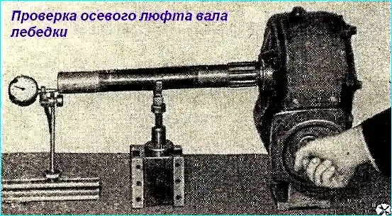
- - Check the tightening of the worm gear. A correctly adjusted shaft should rotate freely and have an axial play of no more than 0.08 mm (Fig. 3).
- - Select a cam clutch according to the splines of the drum shaft so that it moves freely with the force of your hand.
- - Place the crossbar so that the axis of the crossbar mounting holes is located below the axis of the bushing.
- - After installing the cable stirrup, insert the cable so that its end coming out of the stirrup is 35 mm.
- - Grease the drum bushings and shaft crossbars through the grease nipples of the drum and shaft, lubricate the splines of the clutch and shaft with oil used for the engine.
- - Adjust the automatic brake as indicated above.
Pour spindle oil into the gearbox housing to the level of the inspection hole plugs and run the winch on the stand for 15-20 minutes at 700-800 rpm.
During the winch run-in, check the operation of the worm gear, the absence of oil through the oil seal, bolted connections and connectors. After running-in, drain the oil from the gearbox housing.
Technical conditions for processing pressed bushings. Mutual runout of the surfaces of the holes of the winch drum bushings - no more than 0.05 mm.
Mutual runout of the surfaces of the hole of the crankcase bushing and the hole for the gearbox cover is no more than 0.08 mm.
The runout of the centering shoulder of the flange of the gearbox cover relative to the surface of the bushing hole is no more than 0.08 mm.
The winch cardan shafts must be disassembled in the following order.
- 1. Remove the cardan shaft from the splined end of the shaft.
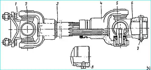
- 2. Press out the bearings of the crosspiece 5 (Fig. 4) from the holes of the sliding fork 4, having first removed their retaining rings 2.
- 3. Together with the crosspiece 5, remove the fork with a threaded hole at its end when disassembling the rear propeller shaft and the fork with a through hole for the safety pin when disassembling the front shaft.
- 4. Remove the retaining rings, press out the bearings from the holes of the fork and take out the crosspiece.
- Flare and press out the collar, take out the sliding fork oil seal.
- 5. Press out the bearings of the crosspiece from the holes of the welded fork of the propeller shaft, having first removed their retaining rings.
- 6. Remove the cardan flange 1 together with the crosspiece.
- 7. Remove the retaining rings, press the bearings out of the flange holes and take out the crosspiece.
- 8. Unscrew the grease nipples and safety valves from the crosspieces.
Determine the technical condition of the winch cardan shaft parts. Clean the disassembled parts from old grease, dirt and metal particles.
Wash and wipe the bearings. Inspect the parts for faults.
To check the serviceability of the crosspiece safety valve, screw the valve into a tee into which a pressure gauge is screwed and a syringe with grease used for the gearbox is connected.
The full opening of the valve should correspond to a pressure of 1-3.5 kg/cm 2. Replace faulty valves.
Crosspiece and cardan bearings. If the bearings swing on the tenon or the tenons have worn to a diameter less than 16.26 mm, replace the crosspiece assembly with the bearings.
If there is a gap between the ends of the bearings and the needle holders, press the needle holder until it stops.
Replace the bearing assembly with the seal if individual needles are deformed or if at least one of them is lost, as well as if the seal is worn.
Forks and cardan shafts. Replace worn parts of the splined connection.
The cardan forks with increased wear and tear of the bearing holes (diameter greater than 30.02 mm) are subject to replacement.
Replace the sliding fork seals of the cardans with new ones.
Assembly of cardan shafts. When assembling, insert the sliding fork seal into the collar and press it onto the fork until it stops so that the grooves and projections of the seal and the spline coincide, and crimp.
Put the crosspieces with the grease nipple facing outward.
Put 1-13 grease into the cavity of the sliding fork and place the fork on the splined end of the shaft so that it lies in the plane of the welded fork.
Disassemble the intermediate support of the winch cardan shafts in the following order.
- Punch and unscrew nuts 5 (Fig. 5) of flanges 4 cardans, remove washers and flanges.
- Press out the shaft together with one of the bearings.
- Press out the second bearing from the bracket of the intermediate support.
- Press the bearing off the shaft.
Determining the technical condition of the intermediate support parts. Check for grease in the bearings.
To do this, remove the outer, inner and middle rubber split spring rings from one side of the bearing.
If there is no grease, fill the inner cavity of the bearing with one of the lubricants TSIA-TIM-201,
TSIA-TIM-202 or OKB-122-7. Put the rings back. If there is a lot of play in the bearings, replace them.
Assembling the intermediate support. The intermediate support is assembled in the reverse order of disassembly.
When assembling the intermediate support, tighten the nuts to a torque of 30-33 kgm and score them.
cardan joint flanges
Disassemble the winch cable guide in the following sequence:
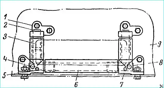
- 1. Remove the uppere brackets 1 (Fig. 6) of the guide rollers.
- 2. Remove the axles, remove the vertical rollers 3.
- 3. Remove the lower brackets 5 of the guide rollers together with the horizontal roller 6.
- 4. Knock out one of the pins securing the horizontal roller axle, remove the bracket and the guide roller.
- 5. Knock out the second pin securing the axle and remove the horizontal axle 8.
Determining the technical condition of the parts and assembling the winch cable guide device
Clean the parts of the cable guide device from old grease, dirt and metal particles and inspect.
Check the condition of the tombac bushings of the rollers. In case of severe wear and tear, replace the bushings.
Finish the bushing holes after pressing into the rollers, ensuring a clearance in the bushing-axle joint within 0.14-0.42 mm.
Replace bent or severely worn roller axles. Replace the roller brackets if there are cracks or significant end wear.
Assemble the winch cable guide in the reverse order of disassembly.
")

")
")
")
")
")
")
")