The vehicles are equipped with a drum-type shoe hand brake with a mechanical drive
The brakes are identical in design and differ only in the location of the mounting holes on the shields and the drives.
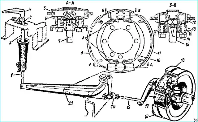
The GAZ-66 brake device and its drive are shown in Fig. 1.
Handbrake maintenance
Adjusting the gaps between the linings and the brake drum
As the friction linings of the brake shoes wear out, the gap between the linings and the brake drum is restored by tightening the adjusting screw.
It is recommended to adjust the brakes of the GAZ-53A in the following sequence.
Hang up the rear wheel (on one side) using a jack.
Put the brake lever in the extreme forward position.
Tighten the brake adjusting screw so that the brake drum does not turn due to manual effort.
Loosen the adjusting screw so that the drum rotates freely.
If after the specified adjustment the lever travel is still large, then the brake drive needs adjustment. To do this, you need to:
- - tighten the brake adjusting screw so that the brake drum does not turn with the force of your hands;
- - adjust the length of the rod with the adjusting fork until the holes in the fork match the hole in the lever, eliminating all the gaps in the connections;
- - increase the length of the rod by unscrewing the adjusting fork by 2-3 turns. Tighten the fork lock nut, insert the pin (head up) and cotter pin;
- - loosen the adjusting screw so that the drum rotates freely. When adjusted correctly, the lever travel should be 3-5 teeth.
Adjusting the brakes on a GAZ-66 is similar to adjusting the brakes on a GAZ-53A.
When adjusting, set the rear axle and downshift lever to neutral. Disengage the front axle and release the pull rod to its lowest position.
When adjusted correctly, the drive rod should extend by 10-15 teeth.
Repairing the handbrake
Disassembling and assembling the handbrake should be done as follows.
- 1. Disconnect the front end of the propeller shaft and the drive lever from the rod.
- 2. Remove the drum.
- 3. Loosen the adjusting screw so that the ends of the shoes rest against the housing of the adjusting mechanism.
- 4. Remove the springs pressing the ends of the shoes to the adjusting mechanism.
- 5. Remove the ends of the shoes released from the springs from the guide grooves, and then remove the shoes.
- 6. Remove the release mechanism and take out the shoe pushers, balls and ball housing.
- 7. Take the shoe supports out of the adjusting mechanism housing.
Assemble in the reverse order.
When assembling, lubricate the pushers, balls, ball housing, shoe supports of the adjusting mechanism, and the shoe support surfaces with a thin layer of grease 1-13 or solid oil.
Make sure that the grease does not get on the shoe linings.
Inspection and repair
Inspect the working surface of the drum. If there are any scoring marks, bore the drum. The permissible boring diameter is no more than 221.5 mm.
Inspect the working surface of the friction linings and, if the surface is tarred, clean it with sandpaper; if it is oiled, wash it with gasoline.
If the rivet recess depth is less than 0.5 mm, replace the linings.
Replace the linings in the same way as the wheel brake linings.
The ends of the pads must not have wear that prevents the pads from sliding freely in the grooves of the pushers and support pins.
The presence of wear leads to incomplete release of the brake, its heating and premature wear of the brake linings. Therefore, such pads must be replaced with new ones.
Crushed ends of the pads can be cleaned only if it is possible to cyanide them to a depth of at least 0.08 mm and hardening.
Grind the riveted pads to the shoes so that their radius matches the radius of the bored drum.
Clean up the burrs formed by the balls on the tappet bevels.
If the balls are corroded or there are dents on the surface, replace them. Ball diameter 11.9 mm.
Nominal and repair dimensions of the central brake drum
Diameter of the drum working surface, mm:
- - nominal size - 220+0.185;
- - first repair - 221+0.185;
- - second repair - 222+0.185;
- - third repair - 223+0.185;
- - fourth repair - 224+0.185
The runout of the drum working surface relative to the central hole should be no more than 0.3 mm. Cavities on the working surface of the drum are not allowed.
Only new friction linings must be installed on the brake shoes, which must fit tightly to the surface of the shoe.
A 0.2 mm feeler gauge must not pass between the lining and the rim of the shoe by more than 15 mm.
Nominal and repair dimensions of the working surface of the central brake shoes
Radius of the outer surface of the lining, mm:
- - nominal size - 110.0+0.05;
- - first repair - 110.5+0.05;
- - second repair - 111.0+0.05;
- - third repair - 111.5+0.05;
- - fourth repair - 112.0+0.05;
The rivet heads must be 2.0 mm below the friction lining.
Gluing the friction linings to the pads with heat-resistant structural adhesives is allowed.
The pads with glued linings must be subjected to a random shear test (see testing the front and rear brake pads).
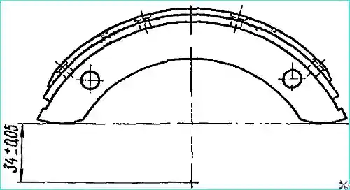
The pads assembled with the linings must have a working surface radius corresponding to the size of the brake drum (Table 1).
The runout of the working surface of the lining when installing the shoe assembly according to the dimensions specified in the manufacturer's drawings (Fig. 2) should not exceed 0.20 mm.
The housings of the expansion and adjustment mechanisms of the central brake can have nominal, repair and acceptable without repair dimensions of the holes for the pushers and shoe supports.
When assembling the central brake, the parts of the expansion and adjustment mechanism must be lubricated with grease.
After installing the central brake and brake drum on the gearbox, adjustment must be made. The adjustment is carried out in the following order:
- - set the central brake lever to the extreme forward position;
- - tighten the adjusting screw so that the brake drum does not turn from the force of the handle;
- - tighten the spherical nut of the rod so that the drive lever rests against the ball housing, then loosen the spherical nut by 2-3 turns and tighten the lock nut;
- - loosen the adjusting screw so that the drum turns without touching the pads.
After finishing adjusting the central brake, it is necessary to check the cotter pin of the brake drive lever.
")

")
")
")
")
")
")
")