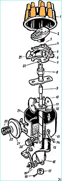
The GAZ-53A and GAZ-66 vehicles use the P1Z-V breaker-distributor (Fig. 1), and the GAZ-66-0Z vehicle uses the P105.
The breaker-distributor shaft is driven by a gear from the camshaft, which rotates clockwise (when viewed from the cover side).
The breaker-distributor has a centrifugal and vacuum ignition timing regulator.
Maintenance of the breaker-distributor
The breaker-distributor must be periodically lubricated, checked and adjusted the gap between the breaker contacts, monitor the condition of the distributor parts and their cleanliness.
A loosely fastened breaker-distributor (maybe turned by hand) must be securely fastened with a fastening nut and tightened with an octane corrector nut, after checking the correctness of the ignition setting and, if necessary, setting the ignition.
Carefully wipe the breaker-distributor cover inside and out with a cloth soaked in clean gasoline.
Carefully check the cover and rotor for cracks or traces of spark breakdown and significant burning or corrosion of the cover electrodes and the rotor current-carrying plate.
Burn on the end surfaces of the rotor current-carrying plate and the cover electrodes indicates an excessively large radial gap between the current-carrying plate and the electrodes. In this case, the cover or rotor must be replaced.
If the cover or rotor shows no signs of damage, carefully clean (wipe) the burnt areas of the cover electrodes and the rotor plate with a cloth slightly moistened in clean gasoline or refined carbon tetrachloride.
Do not clean these areas with a file, as this will increase the gaps between the rotor current-carrying plate and the cover electrodes and cause ignition interruptions.
The high-voltage wires must be tightly inserted into the cover sockets.
Burns and corrosion on the inner surface of the electrode (in the cover sockets) indicate that the wire does not reach the electrode or is poorly held in the socket by the spring contact tip.
In this case, clean the spring tip and insert it into the socket as far as it will go.
If the wire is weakly held in the socket, spread petals of the spring tip.
It should be taken into account that the occurrence of an additional spark gap in the high-voltage circuit as a result of a loose fit of the high-voltage wires in the cover sockets can lead to burnout of the plastic cover, failure of the ignition coil, and disruption of the normal operation of the engine.
If necessary, blow out the inner surface of the breaker-distributor with compressed air.
Periodically check and tighten the fastening of the vacuum regulator pipeline of the breaker-distributor.
Check for jamming, the central contact should move freely in the cover socket.
When lubricating the breaker-distributor, be careful not to let oil get on the breaker contacts, since oil significantly increases the burning of the contacts and reduces their service life.
If oil or dirt gets on the breaker contacts, be sure to wipe the contacts with chamois leather, soaked in clean gasoline.
Clean the contacts only if their condition causes interruptions in the ignition system and not more often than after 12,000 km of vehicle mileage.
When cleaning the contacts, remove the bump on one of them and smooth out the surface of the other, on which a depression (crater) is formed.
It is not recommended to remove this depression completely. Contacts should be cleaned with a clean abrasive tool.
To ensure that the contact surfaces are strictly parallel, it is recommended to press the lever with your finger when cleaning.
Contacts should not be cleaned with sandpaper, a file, or a coin.
During operation, it is permissible to clean (brighten) the contacts using a plate installed on the probe, which is attached to the car.
After cleaning the contacts, blow air on the breaker panel, wipe the contacts with chamois leather slightly moistened with clean gasoline, and set the normal gap between contacts.
If the breaker contacts are significantly burned or worn, replace the breaker stand and lever.
An abnormal gap between the breaker contacts, burning or contamination of the contact surface causes interruptions in the operation of the ignition system and makes it difficult to start the engine, especially in cold weather.
A condition for long-term and reliable operation of the breaker is the parallelism of the contacts and their good fit to each other over the entire surface.
It should be remembered that the tungsten contacts of the breaker are thin, and therefore frequent cleaning inevitably leads to a reduction in the service life of the contacts.
Check the tension of the breaker lever spring.
It is periodically recommended to remove the breaker-distributor and check the operation of the breaker-distributor, centrifugal and vacuum regulators on a stand such as SPZ-6.
In the absence of stand, check the centrifugal regulator for jamming.
The easiest way to do this is to check whether the rotor of the breaker-distributor returns freely to its original position if you turn it by hand relative to the fixed shaft and then release it.
A breaker-distributor with faulty regulators is subject to repair or replacement.
Repair of regulators consists of replacing worn or faulty parts with mandatory adjustment after this, ensuring that the characteristics of the regulators correspond to the values specified above.
The centrifugal regulator is adjusted by changing the tension of the springs 12 weights (see Fig. 1) by bending the posts on which it is attached.
The vacuum regulator is adjusted by changing the number of adjusting washers placed between the spring and the nut of the machine body.
Adjusting the gap between the breaker contacts and setting the ignition.
The reliability of the ignition system depends primarily on the gap between the breaker contacts and the cleanliness of the contacts.
Centrifugal ignition timing regulator
The ignition timing angle during operation of the centrifugal regulator changes depending on the number of revolutions of the breaker-distributor shaft.
Mismatch of the ignition timing angles to the number of revolutions of the breaker-distributor shaft is usually associated with the seizure of the centrifugal regulator weights or with the weakening of their springs and causes detonation, a decrease in engine power, and an increase in fuel consumption.
Table 1
- Number of revolutions of the breaker-distributor per minute 200 - Spark advance angle by the breaker-distributor cam, degrees - 0 - 2;
- Number of revolutions of the breaker-distributor per minute 500 - Spark advance angle by the breaker-distributor cam, degrees - 3 - 5;
- Number of revolutions of the breaker-distributor per minute 1000 - Spark advance angle by the breaker-distributor cam, degrees - 8 - 10;
- Number of revolutions of the breaker-distributor per minute 1500 - Spark advance angle by the breaker-distributor cam, degrees - 12.5 - 15.5;
Vacuum ignition advance regulator
Characteristics of the vacuum ignition timing regulator:
- Vacuum, mm Hg - 100 - Ignition timing angle relative to the distributor breaker cam, degrees - 0-2;
- Vacuum, mm Hg - 200 - Ignition timing angle relative to the distributor breaker cam, degrees - 4-7;
- Vacuum, mm Hg - 280 - Ignition timing angle relative to the distributor breaker cam, degrees - 7.0-10.0;
Failure of the vacuum regulator or its normal operation causes an increase in fuel consumption, especially when driving with a partial load.
To adjust the gap between the breaker contacts, it is necessary to:
release the spring holders and remove the breaker-distributor cover, and shielded breaker-distributor, first remove the shield;
- - rotate the engine crankshaft with the starting handle, set the cam so that there is a maximum gap between the contacts;
- - check the gap between the contacts with a feeler gauge. The feeler gauge should enter the gap without squeezing the lever. The gap should be within 0.30-0.40 mm.
If the gap is greater or less than specified, loosen the locking screw of the fixed contact post and, turning the adjusting eccentric screw, set the normal gap;
- - tighten the locking screw and recheck the gap between the contacts.
When checking the breaker-distributor on the stand, instead of measuring the gap, measure the angle of rotation of the breaker-distributor shaft at which the contacts are in the closed state. It should be within 28-33˚;
- - install and secure the distributor cover.
The order of operations when installing the ignition is as follows
Remove the distributor cover and rotor check the gap between the breaker contacts (adjust the gap if necessary). Put the rotor back in place.
Unscrew the spark plug of the first cylinder.
Having covered the opening of the spark plug of the first cylinder with your finger, turn the crankshaft of the engine with the starting handle until air begins to come out from under your finger. This will happen at the beginning of the compression stroke in the first cylinder of the engine.
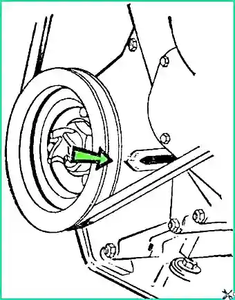
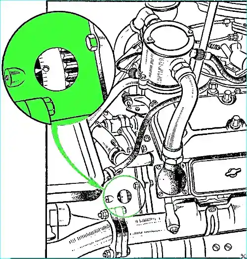
After making sure that compression has begun, carefully turn the engine shaft until the pointer aligns with the mark on the crankshaft pulley on the GAZ-53A vehicle (Fig. 2) and with the ball stamped into the flywheel on the GAZ-66 and GAZ-66-03 vehicles (Fig. 3).
Make sure that the rotor is opposite the inner contact of the cover, connected to the wire, to the spark plug of the first cylinder.
Use the smooth adjustment nuts to set the octane corrector scale to zero division.
Loosen the nut securing the breaker-distributor column and slightly turn the breaker-distributor housing clockwise so that the breaker contacts close.
Connect one of the wires of the portable lamp to the low voltage terminal on the coil (to which the wire going to the breaker is attached), and the second to the engine ground.
You can also use an underhood lamp for this purpose.
Turn on the ignition and carefully turn the breaker housing counterclockwise until the bulb flashes.
You need to stop the rotation of the breaker exactly at the moment of flashing bulbs. If this fails, repeat the operation.
Holding the breaker housing from turning, tighten the breaker column mounting nut, put the distributor cap and central wire in place.
Check the correct connection of the spark plug wires, starting with the first cylinder.
The wires must be connected in the order 1, 5, 4, 2, 6, 3, 7, 8, counting clockwise.
After each ignition setting, adjustment of the breaker contact gap, as well as a change in the grade of gasoline, you should clarify the setting of the ignition moment of the combustible mixture by listening to the engine while the car is moving.
The ignition setting must be adjusted using the octane corrector, without loosening the column mounting nuts. To do this, simply rotate the manual adjustment nuts (loosening one and tightening the other).
Moving the arrow by one division of the octane corrector scale corresponds to changing the ignition setting by 2°, counted along the crankshaft.
When turning the breaker housing counterclockwise, the ignition setting will be earlier, clockwise — later.
Check the engine operation when fine-tuning the ignition setting as follows. Warm up the engine to a temperature of 80-90°C.
Moving in direct gear on a level road at a speed of 25-30 km/h, accelerate the car by sharply pressing the throttle pedal all the way down.
If you observe minor and short-term detonation, then the ignition timing is set correctly.
If there is strong detonation, turn the distributor housing one division of the octane corrector scale clockwise.
If there is no detonation at all, turn the distributor housing one division counterclockwise.
You should always work with an ignition setting that gives only slight detonation under high engine load.
If the ignition is set too early, when strong detonation is heard, the cylinder head gasket may be broken and the valves and piston.
If the ignition is too late, fuel consumption increases sharply and the engine overheats.
Repairing the breaker-distributor
Disassemble the breaker-distributor to be repaired in the following order.
Remove the cover and rotor, first remove the screen for the shielded breaker-distributor.
Mark the position of the vacuum regulator on the breaker housing with marks and remove it.
Remove the low voltage terminal.
Remove the breaker panel. In the case of a shielded breaker, first remove the capacitor.
Unscrew the two screws of the holders from the bottom of the panel and separate the movable panel from the fixed one.
Remove the movable contact.
Remove the stand with the fixed contact.
Remove the cam with the plate.
Knock out the rivet in the shaft shank and remove the shaft with the centrifugal regulator.
Assemble the breaker-distributor in reverse order. Before assembly, lubricate the breaker-distributor.
Inspect and check the cover and rotor. Wipe the cover and rotor thoroughly.
Wipe the high-voltage wire terminal sockets of the cover especially thoroughly.
Wipe the terminals inside the cover and the rotor plate without using tools, since cleaning the terminals and plates with a tool can lead to an increase in the gap in the high-voltage circuit, which is unacceptable.
Check whether the central contact of the cover moves freely, check the ohmic resistance of the central contact using an ohmmeter.
The resistance should be within 8000-13000 Ohms.
The rotor should fit tightly on the cam. Check the rotor socket for a flat spring.
Inspect and check the breaker contacts. The contact surface should be clean and grey.
If the contacts are burnt or metal is transferred from one contact to another, clean them with a fine abrasive block.
After cleaning the contacts, they should be washed. Replace badly worn contacts.
When installing contacts on the panel, make sure that the contacts are parallel to each other and that their diameters do not shift relative to each other.
Contact parallelism is achieved by proper cleaning and bending of the fixed contact post.
The correct position of the contacts relative to each other is adjusted using washers installed on the lever axis.
When installing the lever, pay attention to the tightness of the lever fit on the axis.
If the axis is worn or the hole is worn out, replace the parts.
After installing the lever, check the contact pressure, which should be within 500-600 G (Fig. 4).
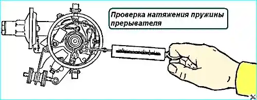
To adjust the clamping force, use the oval slot in the spring, and if this is not enough, remove the lever and bend the spring in one direction or another to achieve the required force.
The gap between the contacts is adjusted on the assembled breaker-distributor.
If the normal gap cannot be adjusted, this indicates severe wear of the lever cushion. Such a lever is subject to replacement.
Inspection and testing of the breaker panel and capacitor. Inspect and check the serviceability of the conductors connecting the movable contact to the terminal and the movable plate to the fixed one.
Check for play between the panels. If there is play, separate the panels, wash the bearing and fill with fresh L3158 grease.
Turn the outer ring of the bearing at a small angle to select the position in which the play is the smallest and assemble the panel.
If the play is large and cannot be eliminated, replace the entire panel.
Remove the felt, wash in gasoline, dry, soak in engine oil, squeeze out and put back in place.
Cut off the coked part of the felt or replace the felt.
When assembling the breaker-distributor, make sure that the felt touches the cam and lubricates its edges.
The capacitor is tested on the stand by checking its capacity and the serviceability of the insulation.
Inspecting the cam. When inspecting the cam, pay special attention to the wear of the cam faces and the presence of ring marks on them.
If there is wear on the cam face, it should be replaced. If the cam has play when installed on the shaft, replace the cam or shaft.
Inspect and check the housing of the breaker-distributor with a centrifugal regulator. Check for wear on the shaft pin. If there is wear, replace the shaft.
Check for jamming of the trucks on the axles. If there is radial play of the shaft up to 0.2-0.3 mm, replace the copper-graphite liners. To do this, saw off the head of the shaft rivet and knock it out.
Remove the shaft with the centrifugal regulator from the housing. The roller with wear in the places of the liners is subject to replacement.
Press out the worn liners and press in new ones, and after pressing, ream them with a reamer to a diameter of 12.7+0.012mm.
Checking the vacuum regulator. The correct operation of the vacuum regulator is checked on the assembled breaker-distributor, on a test bench.
When completely disassembling the breaker-distributor, check the vacuum regulator for leaks. If the diaphragm is damaged, the regulator must be replaced.
After inspection and replacement of parts, the breaker-distributor is assembled, lubricated and a control check is performed with adjustment of all parameters.
Malfunctions of the breaker-distributor and how to eliminate them
Interruptions in the operation of the ignition system or lack of spark
Burning of contacts - Clean the contacts and adjust
Spring weakening - Measure the spring force and adjust the tension force
Broken wire connecting the terminal to the moving contact - Check with a test lamp and repair the damage
Broken wire between the movable plate of the breaker and the fixed one - Check with a test lamp and repair the damage
Breakdown or contamination of the rotor and cover - Thoroughly wipe the rotor and cover
Rotor and cover with breakdowns, cracks and burnouts are subject to replacement
Large radial play of the breaker-distributor shaft - If the radial play of the breaker-distributor shaft is more than 0.2-0.3 mm, then it is necessary to replace the liners
Capacitor malfunction - Check the serviceability of the capacitor
Severe detonation engine when pressing the throttle pedal quickly
Ignition too early for this type of fuel - Reduce the advance angle using an octane corrector
Increased fuel consumption and decreased engine power
Jamming of the centrifugal ignition advance regulator weights - Check on a bench and repair the damage
Increased fuel consumption when driving without a load
Faulty vacuum ignition advance regulator - Check the tube connecting the regulator to the carburetor.
Remove the breaker-distributor and check if there is gasoline in the regulator cavity, check the regulator for leaks
")

")
")
")
")
")
")
")