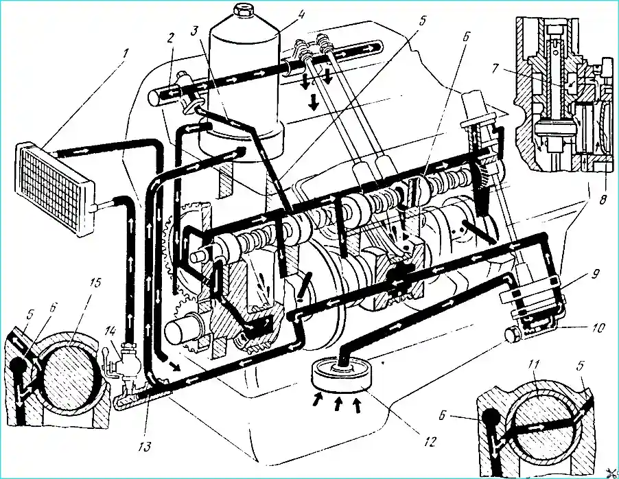
The engines have a mixed (pressure and splash) lubrication system
Under pressure, oil is supplied to the main and connecting rod bearings of the crankshaft, to the camshaft bearings
Oil is supplied to the rocker arm bushings with pulsating pressure through the hollow rocker arm axles, into which it enters through channels coming from the second and fourth camshaft bearings.
Oil is supplied to the remaining engine parts by gravity and splash.
To cool the oil, the engines are equipped with an oil cooler installed in front of the cooling system radiator.
The drop in pressure in the lubrication system is mainly due to wear of the oil pump parts or the crankshaft and camshaft bearings.
If the wear is significant, the oil pump starts to work noisily. To identify pump faults, it must be removed from the engine and disassembled.
However, you should only start disassembling the pump after checking the condition of the pressure-reducing valve, since it can be the cause of abnormal pressure in the oil system (the spring is weak, the plunger is jammed, etc.).
To make sure that the pressure-reducing valve is working properly, you need to unscrew its plug, remove the spring and make sure that the plunger moves freely in its seat, without jamming, and that the spring is in normal condition.
The length of the spring in a free state should be 50 mm. The valve spring force when compressed by 10 mm should be equal to 4.6 kgf.
If the force weakens, replace the spring with a new one, since it is strictly prohibited to put washers under it or stretch it to increase the force.
Disassembling the oil pump
- 1. Remove the pump together with the gasket from the cylinder block.
- 2. Remove the lower section housing with the driven gear and gasket.
- 3. Remove the lower section drive gear of the oil pump and the segment key of the gear from the pump shaft.
- 4. Remove the oil pump partition with the gasket.
- 5. Remove the driven gear of the upper section of the pump from the housing.
- 6. Remove the shaft with the drive gear of the upper section from the pump body.
- 7. After disassembling the pump, thoroughly wash, dry and inspect all its parts.
- 8. If wear from the gear is found on the partition of the oil pump, grind it until traces of wear are eliminated. If the section housings are heavily worn, replace the pump with a new one.
The following should be kept in mind during repairs.
The distance from the end of the shaft with a hexagonal hole to the upper end of the drive gear of the upper pump section should be 40 ± 0.15 mm.
A hole with a diameter of 4 mm for the pin for fastening the gear on the pump shaft is drilled to a depth of 23 ± 0.5 mm at a distance of 15 mm from the end of the gear.
The pin must not rise above the plane of the tooth cavity.
When pressing out the axles of the driven gears from the pump section housings, the latter are heated to 100-120 ° C, and when pressing in - to 160-170 ° C, and the axles are cooled in a dry ice.
When pressing the driven gear axle into the upper section of the pump housing, it is necessary to maintain a size of 3 ± 0.25 mm, and into the lower section housing 0.5 ± 0.25 mm from the end of the housing to the end of the axle.
Assemble the pump in the reverse order.
When assembling the pump, the paronite or cardboard gaskets of the housings should be changed (their thickness is 0.3-0.4 mm).
It is unacceptable to use shellac or other sealing agents, as well as to increase the thickness of the gaskets, since this reduces the performance of the oil pump.
Before installing on the engine, the pump is filled with oil, since a dry pump at the very beginning of engine operation will not supply oil to the rubbing surfaces, which will lead to their scoring and failure.
Disassembling the oil pump drive (Fig. 2). Press out pin 6 of the drive gear using a punch with a diameter of 3 mm.
1. Remove the hexagonal shaft 7 of the oil pump drive.
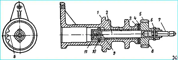
- 2. Press out the sh drive pinion 5 using a mandrel, for which purpose install the drive housing with its upper end on a plate with an opening for the free exit of the shaft assembled with the thrust sleeve.
- 3. Remove thrust washers 3 and 4 and remove shaft 2 from the breaker-distributor drive housing.
- 4. Press out pin 10 of thrust sleeve 11 of drive shaft and press in sleeve.
After disassembling, wash all drive parts and inspect thoroughly.
Assembly of breaker-distributor drive. Press thrust sleeve 11 onto breaker-distributor drive shaft, maintaining size of 19 ± 0.1 mm from shaft end to lower end of sleeve.
Drill hole with diameter of 4+0.03 mm in thrust sleeve at distance of 13 ± 0.15 mm from end.
Axis of hole in sleeve should coincide with axis of hole in breaker-distributor drive shaft.
Countersink chamfers 0.8 mm deep at an angle of 90˚ in a hole with a diameter of 4 mm on both sides.
Press pin 10 into the hole and rivet it on both sides.
Lubricate the assembled shaft with clean engine oil, insert it into the housing of the breaker-distributor drive and test its ease of rotation by hand.
Install thrust washers on the shaft, first steel 3, and then bronze 4.
Press gear 5 onto shaft 2, maintaining a gap of 0.15-0.55 mm between the ends of the gear and the bronze thrust washer.
Axis 9 of the groove on the shaft should be parallel to the axis passing through the middle of the depression 8 on the lower end of the gear, permissible deviation ± 2˚.
Drill a hole with a diameter of 4+0.03 mm, maintaining a distance of 9 ± 0.15 mm from the axis of the hole to the end of the gear hub.
When drilling a hole, the shaft assembly must be pressed by the end of the thrust sleeve 11 to the housing 1 of the breaker-distributor drive.
The axis of the hole must pass through the axis and the middle of the face of the shaft 7. The permissible deviation is no more than 0.1 mm.
Insert the hexagonal shaft 7 of the oil pump drive into the hexagonal hole in the end of shaft 2 of the drive and press a pin with a diameter of 4 mm into the hole.
Rivet the pin on both sides.
Check the ease of rotation of the shaft, the gap between the thrust washer and the end face of the drive gear and the displacement of the center of the tooth groove of the breaker-distributor drive gear relative to the axis of the shaft groove.
Disassembling the centrifugal oil filter. Remove the casing.
Carefully remove the rotor cup by the nut, holding the rotor from rotating.
By swinging the rotor on the axis, determine the radial clearance in the rotor bushings.
A noticeable movement of the rotor indicates wear of the bushings, and the rotor must be replaced.
Remove the rotor together with the washer.
When removing the rotor, ensure that the upper ring of the thrust bearing is not lifted together with the rotor, as it may fall into the filter housing, and from there into the timing gear cover and into the engine crankcase.
After disassembling the filter, thoroughly wash all its parts in kerosene and blow with compressed air.
Inspect the jets and, if they are clogged, unscrew them to clean them.
Each jet should be installed in its own socket, since they are processed together with the rotor, so it is not recommended to unscrew both jets from the rotor at once.
To clean the jet, insert a 5 mm drill into its hole and, rotating it by hand, remove all deposits.
After this, wash the jet again in kerosene and blow with compressed air through the nozzle hole.
When installing the jet in place, pay attention to the coincidence of one of the faces of the jet head with the mark applied to the rotor boss, since a violation of the location of the nozzle holes causes oil to be thrown into the rotor rotation zone, and this greatly slows down its rotation.
To replace the sealing gasket of the nut remove the spring retaining ring from the nut of the rotor cup and remove the nut from the rotor cup.
Assemble the filter in the reverse order.
When assembling, make sure that the sealing gaskets are not squeezed out of their seats and that the filter rotor rotates freely on the axis.