The steering of the GAZ-53A car consists of a steering mechanism with a steering wheel shaft, a steering column and steering rods
The steering of the GAZ-66 car, in addition, has a hydraulic booster.
The working pair of the steering mechanism is a globoidal worm and a three-ridge roller.
The steering mechanism of the GAZ-5ZA car is shown in Fig. 1.
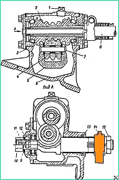
In terms of the main parts (worm, roller, steering bipod shaft, bearings, side cover), the steering mechanisms of the GAZ-53A and GAZ-66 cars are interchangeable.
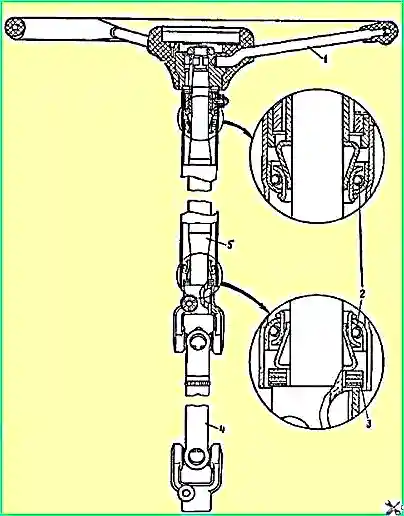
Due to the fact that the cab of the GAZ-66 car is tilted forward, the steering shaft of this car is split and has two universal joints (Fig. 2).
Steering maintenance
For normal steering operation, check the free play of the steering wheel every day before leaving.
With proper adjustment of the steering mechanism and steering rods, there should be no free play of the steering wheel in the position corresponding to straight movement on a GAZ-53A car, and on a GAZ-66 car it should not exceed 10˚ when the engine is running and 30° when the engine is not running engine, which corresponds to 25 and 80 mm when measured on the wheel rim.
If the free play of the steering wheel exceeds the above values by 40 mm, adjust the steering mechanism and tie rods.
The most common cause of increased free play of the steering wheel is the formation of gaps in the steering linkage joints, so you should first check and, if necessary, adjust the linkage joints.
When adjusting the steering mechanism, first check that the worm bearings are adjusted correctly and, if necessary, adjust them.
Adjusting bearings
The worm bearings are adjusted when axial movement of the steering gear worm occurs.
This movement on a GAZ-53A car can be felt if you grab the steering column with your hand so that your thumb touches the end of the steering wheel hub, hold the steering wheel from rotating with your other hand and swing the hanging wheels from side to side.
To determine the axial movement of the worm in the steering mechanism of the GAZ-66 car, it is necessary, with the cab tilted, to disconnect the fork of the lower cardan of the steering shaft from the worm shaft and the longitudinal steering rod from the bipod.
If there is axial movement of the worm, then when rocking the bipod it will be easy to feel with your hand the movement of the worm shaft relative to the upper cover of the steering mechanism.
Adjust the worm bearings in the following order:
- - remove the steering mechanism from the car;
- - drain the oil from the steering gear housing;
- - clamp the steering mechanism in a vice by the crankcase flange;
- - remove the lower crankcase cover;
- - carefully use a knife to separate and remove the thin paper gasket;
- - install the bottom cover in place and check the axial movement of the worm. If there is axial movement, then remove the bottom cover, remove the thick gasket, and install the previously removed thin gasket in its place;
- - remove the bipod shaft;
- - check the tightness of the worm bearings. With proper tightening, the force applied to the worm shaft at the radius of the steering wheel circumference should be 0.3-0.5 kg;
- - having assembled the steering mechanism and adjusted the engagement of the worm with the roller, install it on the car.
Adjusting the engagement of the worm with the roller
The engagement of the worm with the roller is adjusted when the worm bearings are correctly adjusted.
To determine the need to adjust the engagement of the worm with the roller:
- - set the steering wheel to a position corresponding to the vehicle moving in a straight line, disconnect the longitudinal steering rod from the bipod, and use an indicator to determine the amount of movement of the end of the bipod when it rocks.
If the movement of the end of the bipod exceeds 0.3 mm, then, without removing the steering mechanism from the car, adjust the gap in the engagement of the worm with the roller in the following order:
- - unscrew the cap nut 8 (see Fig. 1) of the steering mechanism and remove the stopper new washer 7;
- - use a wrench to turn adjusting screw 11 clockwise until the play is eliminated;
- - check on the steering wheel rim the force required to turn the steering wheel about the middle position, and bring it by rotating the adjusting screw to 1.6-2.2 kg
- - put on the lock washer. If one of the holes in the lock washer does not coincide with the pin, then turn the adjusting screw until it matches. In this case, the steering wheel turning force should not exceed the above limits;
- - screw on the cap nut and check the play at the end of the steering arm again;
- - connect the longitudinal steering rod to the bipod.
- - disconnect the turn switch wires;
- - remove the protective casing of the turn switch wires and the switch itself;
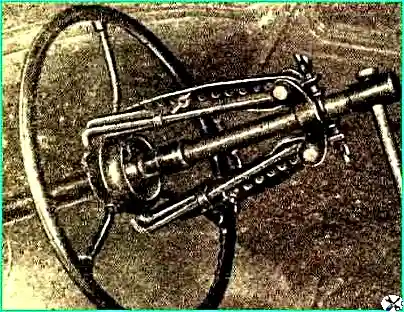
- - remove the steering wheel using a puller (Fig. 3);
- - remove the spring, spacer ring and bearing of the upper part of the steering shaft;
- - remove the trim and the steering column mounting bar;
- - remove the bipod using a puller;
- - unscrew the screws securing the bulkhead seal at the steering column;
- - unscrew the nuts securing the steering gear housing to the frame longitudinal beam and remove the steering gear.
The steering mechanism from the GAZ-66 car must be removed in the following order:
- - remove the signal button by turning it clockwise;
- - remove the spring and plug;
- - remove the plate holding the signal button;
- - disconnect the signal wire;
- - remove the linings securing the steering column to the levers of the clutch and brake pedal bracket;
- - unscrew the nut, remove the bolt securing the lower fork of the steering shaft propeller shaft to the worm shaft and remove the propeller shaft assembly with the column and steering wheel from the worm shaft;
- - remove the bipod using a puller;
- - unscrew the nuts of the bolts securing the steering mechanism housing to the longitudinal beam of the frame and remove the steering mechanism.
The steering mechanism of the GAZ-53A must be disassembled in the following order.
Drain the oil from the steering gear housing.
Loosen the nut of the lower steering column clamp bolt, remove the colony tube, as well as the support washer, O-ring spring, O-ring washer and O-ring.
Clamp the steering mechanism in a vice by the crankcase flange and unscrew the bolts securing the crankcase side cover.
Lightly hit the end of the bipod shaft with a copper or aluminum drift to remove the bipod shaft along with the roller and side cover.
Remove the upper crankcase cover with the upper bearing and gaskets.
Remove the bottom cover, lower bearing with spacers, shaft sealing ring with spring and washer, remove the steering shaft.
The steering mechanism of the GAZ-66 car is disassembled in the same way. At the same time, pay attention to the fact that the wide ring of worm bearings is installed on the side of the top cover (on the steering mechanism of the GAZ-53A car, this ring is installed on the side of the bottom cover).
Steering faults and solutions
Causes of malfunction (Methods of elimination)
Increased free play of the steering wheel:
(on a GAZ-53 car - more than 40 mm, on a GAZ-66 car - more than 120 mm with the engine not running and more than 65 mm with the engine running).
- Increased clearances in the articulated joints of the longitudinal steering rod
Adjust the linkage joints
- Excessive wear of steering rod joint parts
Replace bearings, joints or pins of steering rod joints
- Increased clearance in the engagement of the worm with the roller
Adjust the engagement of the worm with the roller
- The appearance of a gap in the worm bearings
Adjust the worm bearings
Sticking of the steering mechanism required for turning or large force of the steering wheel:
- Wear or destruction of needle bearings of the bipod shaft roller
Repair the bipod shaft or replace it
- - Sticking, squeaking or clicking in the steering mechanism
- - Excessive wear of the roller or worm, chipping and dents on their surfaces
Replace worm or roller
Swinging of the steering wheel with the upper steering shaft of the GAZ-66 car:
- Wear of the rubber bushings of the steering column bracket arms
replace bushings
Axial movement of the steering wheel of a GAZ-66 car:
- The appearance of a gap in the bearings of the upper steering shaft
Adjust the upper steering shaft bearings
Determination of the technical condition of steering mechanism parts
If on slave When the hardened layer is found to be peeling off the surface of the worm, replace it together with the worm shaft. The worm cannot be repaired.
If cracks or dents are found on the surface of the roller, replace it as well. To do this, drill out the head of the roller axle, knock out the axle and remove the roller.
Then insert a new roller and the previously knocked out axle into the groove of the bipod shaft and secure it on the side of the drilled head using electric welding.
During operation, the bronze bushing of the steering gear housing under the bipod shaft is subject to one-sided wear, which reduces the margin for adjusting the engagement of the worm with the roller.
If there is significant wear, replace the bushing and then ream the hole to the nominal size.
After disassembly, it is recommended to check the condition of other parts of the steering mechanism.
Nominal and maximum dimensions to which wear of the main parts is allowed are given in table. 1.
Table 1. Nominal and permissible dimensions of the main parts of the steering mechanism
Diameter of the hole in the crankcase bushing for the bipod shaft:
- - nominal - 35 +0.027 mm;
- - permissible without repair - 35,150 mm
The diameter of the hole in the crankcase for the upper (for GAZ-66) or lower (for GAZ-53A) worm roller bearing:
- - nominal - 68 +0.052 mm;
- - permissible - 68.090 mm
The diameter of the hole in the crankcase for the lower (for GAZ-66) or upper (for GAZ-53A) worm roller bearing:
- - nominal - 66 -0.008 mm;
- - permissible - 66.070 mm
Diameter of the hole for the needle bearing of the bipod shaft roller:
- - nominal - 17.8 +0.030 mm;
- - permissible - 17.860 mm
Diameter of the bipod shaft roller axis:
- - nominal - 12.75 -0.008 mm;
- - permissible - 12.720 mm
Outer diameter of the inner ring of the bipod shaft bearing:
- - nominal - 25 -0.014 mm;
- - permissible - 24.960 mm
Assembling and installing the steering mechanism
The steering mechanism is assembled and installed on the car in the reverse order of disassembly and removal from the car.
During the assembly process, the worm bearings and the engagement of the worm with the roller are adjusted.
When assembling the steering shaft with the steering column and steering wheel of a GAZ-66 car, adjust the bearings of the upper part of the steering shaft using adjusting washers 3‚ (see Fig. 2), which are installed between the end of the upper cardan fork and the spacer sleeve of the lower bearing.
After adjustment, the steering shaft should have no axial play and should rotate easily.
")

")
")
")
")
")
")
")