The transfer case (Fig. 1) has two gears: direct and downshifting
To reduce the amount of work during operation, the transfer case uses ball bearings that do not require adjustments.
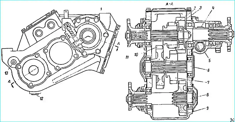
The transfer case is controlled by two levers. The left lever is used to engage the front axle and has two positions: forward - the axle is engaged and rear - the axle is disengaged.
The right lever is used to change gears in the transfer case and has three positions: forward - direct gear is engaged; neutral (middle) position and reverse — downshift is engaged.
The gearshift mechanism of the transfer case is equipped with a locking device that prevents the possibility of engaging a low gear with the front axle disengaged, as well as disengaging the front axle with a low gear engaged.
The locking device protects the cardan transmission and rear axle parts from overload.
Transfer case maintenance
Transfer case maintenance during operation consists of checking the fastening, maintaining the required lubrication level and periodically changing the oil in the crankcase.
In some cases, troubleshooting requires removing the transfer case from the vehicle and disassembling it.
Depending on the nature of the malfunction, disassembly can be partial or complete
Transfer case malfunctions and how to eliminate them
- Causes malfunctions
Remedies
Increased noise during operation of the transfer case:
- Increased lateral clearance in the engagement of gears as a result of wear of their teeth
Replace worn gears
- Weak tightening of bearing cap bolts and cardan flange nuts
Tighten bolts and nuts
- Violation of correct engagement of gears due to wear of bearings
Replace worn bearings
Difficult gear shifting:
- Uneven tire pressure on the front and rear wheels. In this case, the front axle does not engage while the vehicle is moving
Equalize the tire pressure
- Seizure in the transfer case control drive, which may be due to bent or worn drive parts
Check the condition of the drive and replace unusable parts
- Crumpling, chips on the ends of the teeth of the engaged gears, which appeared as a result of their frequent engagement with noise and impacts
Replace unusable gears
- Seizure in the splined joints of the drive and intermediate shafts with sliding gears
Replace faulty parts
Self-disengagement of gears while the vehicle is moving:
- Incorrect engagement of gears, which did not ensure full engagement of gear teeth due to significant wear of forks and rods, as well as due to loosening of fork fastening on rods
Replace worn rods and forks, ensuring the required fastening of forks on rods
- Misalignment of gear teeth caused by wear of the following parts: forks and rods (no locking is felt when shifting gears); grooves for forks and splines on rear and front axle engagement gears; transfer case shaft bearings
Replace worn parts and tighten bolts.
When installing new parts, special attention must be paid to ensuring a tight fit of the sliding gears on the drive and intermediate shafts.
In this case, the shafts and sliding gears should be selected so that there is no perceptible angular play of the gears when they slide freely along the splines of both shafts
- Axial movement of the transfer case shafts, as a result of loosening the tightening of the bearing cap mounting bolts, which secure the shafts from axial movement.
Tighten the bolts
Oil leak from the crankcase of the transfer case:
- Wear of the seals and flange surfaces on which the seals operate
Replace worn parts
- Wear of the seals on the rods
Tighten the seal nuts
- Weak tightening of the cover mounting bolts transfer case
Tighten the bolts
- Cracks in the crankcase and covers, damage to the gaskets
Replace defective parts
- Poor operation of the breather (contaminated with dirt)
Clean the breather from dirt or replace it with a new one
Premature wear or destruction of the bearings of the transfer case:
- Violation of the balance of the cardan shafts
Check the balance of the cardan shafts and the condition of the cardan joints
- Weak tightening of the bearing cap bolts
Tighten the bearing cap bolts
Losing of the retaining half rings of the intermediate shaft:
- Poor shaft assembly
Correctly assemble the shaft
Removing the transfer case from the vehicle
Disconnect the transfer case control levers from the rods. Disconnect the horizontal rod of the handbrake from the lever.
Disconnect the intermediate propeller shaft, the front axle drive shaft and the rear axle drive propeller shaft, remove the transfer case.
Disassembling the transfer case
Remove the central brake drum from the flange of the driven shaft.
Punch and unscrew the nut securing the flange of the driven shaft, remove the flange and the central brake.
Remove the cover of the upper hatch and remove the locking balls with springs from the holes.
Unscrew the plug from the hole for the locking sliders. Remove the shift rods, forks and sliders of the rod locking device with the spring from the crankcase.
Unscrew the seal nuts from the crankcase, remove the sealing rings, washers and seals.
Remove the rod protective caps.
Punch and unscrew the drive shaft flange fastening nut. Remove the flange and the ball bearing cover of the drive shaft.
Remove the drive shaft with the bearing assembly and the rear axle and downshift gear from the crankcase.
Unscrew the nipple of the driven gear of the speedometer drive from the bearing cover of the driven shaft and remove the latter from the cover.
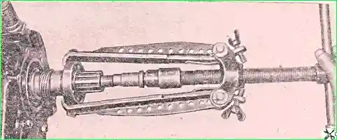
Remove the bearing cover of the driven shaft, remove the rear ball bearing (Fig. 2) and the speedometer drive pinion.
Remove the retaining ring from the groove on the outer race of the front ball bearing of the driven shaft and remove the driven shaft with the bearing from the crankcase through the side hatch.
Remove the intermediate shaft covers.
Punch and unscrew the nut securing the front bearing of the intermediate shaft and remove the retaining half rings from the intermediate shaft.
Press off the front bearing of the intermediate shaft, remove the thrust washer (on some cars there is no thrust washer).
Remove the intermediate shaft assembly with the rear bearing and the front axle engagement and downshift gear pinions.
Unscrew the nut securing the flange of the drive shaft to the front bridge.
Remove the front axle drive shaft covers.
Punch and unscrew the rear ball bearing fastening nut of the front axle drive shaft and press off the bearing.
Remove the front axle drive shaft and gear from the crankcase.
Press off the drive shaft ball bearing.
Remove the retaining ring from the groove of the outer bearing race.
Press off the front ball bearing from the driven shaft.
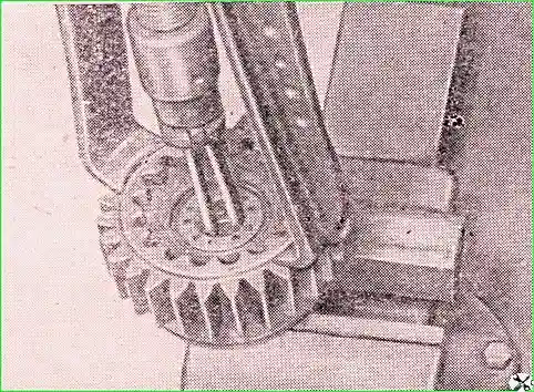
Press out the roller bearing from the driven shaft seat (Fig. 3).
Press the front ball bearing of the drive shaft to the front axle.
Remove the retaining ring from the groove of the outer race of the bearing.
Remove the retaining ring from the groove of the shaft.
Remove the rear bearing of the intermediate shaft.
Determining the technical condition of the transfer case components. Before assembling the transfer case, inspect all components.
The requirements for the technical condition of the transfer case components are similar to the requirements for the gearbox components.
The value of the permissible radial clearance in the transfer case bearings and the method for checking it are the same as for the gearbox bearings, with the exception of the roller bearing of the drive shaft, for which the permissible radial clearance is 0.06 mm when checked under a load of 5 kg.
Assembling the transfer case
Before assembly, lubricate all parts of the transfer case to prevent scoring during the initial period of operation.
When assembling, use only new gaskets and seals. The felt rings of the shift rods should be soaked in a tank with grease for gas valves.
The transfer case should be assembled in the reverse order of disassembly, taking into account the following instructions.
Select the intermediate shaft and the front axle engagement gear, as well as the drive shaft and the rear axle engagement gear and downshift gear for ease of movement.
After selection, the gears should move easily along the splines of the shafts from hand effort, but do not have noticeable axial play.
When pressing ball bearings onto the journal of the drive shaft and onto the front journal of the driven shaft, install the bearings with the groove facing outward.
When pressing the pin of the central brake lever into the cover of the driven shaft, maintain a size of 29.5+0.25mm from the end of the pin to the end of the boss.
Some cars do not have a spacer and oil-scraper rings on the front end of the front axle drive shaft.
After mounting the drive shaft to the front axle, insert the front axle engagement gear and the driven gear of the downshift into the crankcase.
Insert the intermediate shaft assembled with the rear ball bearing into the crankcase through these gears so that the threaded end of the shaft comes out of the hole under bearing.
Put two retaining half rings into the shaft groove, put the downshift gear washer and press the front ball bearing into the housing bore and onto the shaft journal until it stops against the thrust ring.
Before installing, dip the driven gear of the speedometer drive into oil.
Before installing the fitting onto the tailpiece of the driven gear of the speedometer drive, lubricate its threaded part with a thin layer of sealing paste.
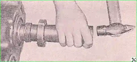
The installation of the rear bearing on the driven shaft is shown in Fig. 4, and in Fig. 5 — press it into the crankcase assembled with the drive shaft.
Punch the bearing and cardan flange fastening nuts over the shaft grooves.
When the rear axle and downshift rod enters the rear opening of the crankcase, press the locking slider with a mandrel.
Tighten the rod seal nuts until they become stiff to rotate.
Place the assembled transfer case on a test bench, fill it with oil (spindle oil at ambient temperature, or nigrol heated to 60-80°C) and check the operation of the transfer case for noise in all gears at 1500 rpm of the drive shaft for 3-5 minutes.
When checking, there should be no noise from the forks touching the gears and the gears touching other details.
No oil leaks from the transfer case anywhere are allowed.
After testing, drain the oil from the transfer case, remove it from the stand, unscrew the nut securing the flange of the driven shaft and install the central brake on the bearing cover of the driven shaft.
Then install the flange of the driven shaft, washer and nut, punch it into the groove of the shaft and screw the drum of the central brake to the flange.
The transfer case is installed on the car in the reverse order of removal.
Adjusting the transfer case
In the transfer case, adjust the gear shift control drive.
The adjustment should ensure complete engagement of the gears. The required position of the control levers is achieved by adjusting the lengths of the rods.
To adjust the position of the lever, unpin the rod pin, remove it from the fork, move the rod until the required gear is fully engaged (the lock should clearly fix the position of the rod), put the lever in the position corresponding to the engaged gear, and set the required rod length by rotating the fork.
Then align the holes in the lever and the rod fork, insert the pin, cotter it and tighten the lock nut on the rod.