The gearbox (Fig. 1) has four forward gears and one reverse gear
The gearbox uses constant mesh gears on the second, third and fourth gears
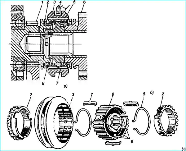
The third and fourth gears are equipped with an inertial type synchronizer consisting of a sliding clutch and a hub. two locking tracks and three crackers pressed to the clutch by two spring rings.
To increase rigidity and improve the accuracy of the installation of the gear rims, the intermediate shaft is made non-separable in the form of a block of four gears.
In addition, to achieve smooth engagement and silent operation of the gearbox, the constant-mesh gears are made with helical teeth.
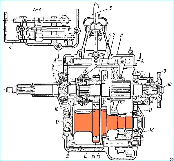
The gearboxes of the GAZ-66 and GAZ-66-02 vehicles differ from the gearbox of the GAZ-53A vehicle in the design of the rear cover (there are no speedometer drive gears, which are installed in the transfer case).
In addition, the GAZ-66-02 gearbox housing has a more accurate tolerance for the size from the axis of the intermediate shaft gear block to the mating surface of the hatch on which the power take-off box is installed.
Gearbox maintenance
Gearbox maintenance consists of checking the fastening, maintaining the required lubrication level and periodically changing the oil in the crankcase.
Gearbox malfunctions and how to eliminate them
- Causes of malfunction
Remedy
- Noise during gearbox operation gears:
- Loose tightening of mounting bolts
Tighten bolts
- Wear or damage of parts
Disassemble gearbox and replace worn parts
- Noise when shifting gears:
- The cause of this defect is malfunctioning synchronizer as a result of wear of threads on conical surfaces of blocking rings and disappearance of gap between ends of blocking ring and straight-toothed crown of corresponding gear
Check gap with feeler gauge, for which remove top cover of gearbox and press blocking ring with coupling to cone of gear. If the gap is less than 0.3 mm, the locking rings should be replaced with new ones
- Difficult gear shifting:
- Incorrect adjustment of the clutch pedal or clutch travel
Adjust the clutch and drive
- Seizure in the gearbox drive due to bent or worn drive parts
Inspect the drive parts and replace faulty parts
- Wear of gearbox mechanism parts
Replace worn parts
- Seizure in the sliding splined joints of the clutch with the synchronizer hub and the driven shaft with the first and reverse gear pinion
Replace faulty parts
- Seizure of gears due to frequent gearbox shifting from higher to lower gears
Note. Frequent and noisy shifting from second to first gear can cause premature wear of the tooth ends, making it difficult to engage first gear.
Replace faulty parts
- Self-disengaging gears while the vehicle is moving:
- Incorrect gear engagement: when engaging a gear, the clutch pedal is released before the gear is fully engaged
Correctly engage the gear
- - Misalignment of gear teeth due to wear of the following parts:
- - shift forks;
- - synchronizer clutch and first reverse gear engagement gear;
- - grooves for forks on the synchronizer clutch and first and reverse gear engagement gear;
- - bearings of the drive, driven and intermediate shafts and their retaining rings
Replace worn parts
- Severe wear of forks and shift rods, as well as loosening of fork fastening on rods
Replace worn rods and forks, ensuring the required fastening of forks on rods
- Weak tightening of gearbox and driven shaft mounting nuts. If the driven shaft has axial movement, this can lead to self-disengagement of gears
Tighten nuts
- Oil leak from gearbox:
- Weak tightening of upper cover mounting bolts (oil leak between cover and crankcase)
Tighten bolts
- Damaged bearing caps and their gaskets
Replace worn parts
- Poor operation of the breather (it is covered with dirt)
Clean the breather from dirt or replace it with a new one
- Formation of cracks in the crankcase and upper cover
Replace parts with cracks
- Wear of the oil seal
Replace the oil seal
- Damage to the driven shaft bearing:
- Violation of the balance of the propeller shaft
Check the balance of the propeller shaft, the condition of the cardans and the bearing of the intermediate support on the GAZ-53A vehicle
- Destruction of the bearing of the drive shaft:
- Weak tightening of bearing cover mounting bolts
Tighten cover mounting bolts
- Incorrect assembly of gearbox and clutch
Correctly assemble gearbox and clutch
Gearbox repair
- Removing the gearbox from the car.
To remove the gearbox from the GAZ-53A car, you need to:
- - place the car on an inspection pit;
- - remove the rubber floor mat and the rubber sealing cap of the upper gearbox cover;
- - remove the gearbox control lever, for which, pressing the lever down, turn the locking cap of the upper cover counterclockwise;
- - close the hole for the lever with a wooden plug;
- - remove the cover;
- - drain oil;
- - disconnect the rear end of the handbrake rod;
- - disconnect the handbrake lever assembly from the top cover of the box;
- - disconnect the clutch release rod;
- - remove the return spring and the clutch release fork;
- - unscrew the oil cap of the clutch release bearing;
- - remove the ventilation hatch of the clutch housing;
- - unscrew the bolts securing the propeller shaft to the flange of the driven shaft of the gearbox;
- - unscrew the bolts securing the intermediate support of the propeller shaft and, without disconnecting the propeller shaft from the flange of the shaft of the drive pinion of the main gear, move it to the side;
- - remove the central brake drum (if the box is dismantled without removing the receiving pipes muffler);
- - disconnect the speedometer drive cable from the gearbox;
- - secure the chain of the lifting device with two bolts securing the upper gearbox cover, disconnect the gearbox from the clutch housing, use the device to move it back and lower it down.
Removing the gearbox and power take-off from the GAZ-66-02 vehicle must be performed in the following sequence:
- 1. Raise the cabin.
- 2. Unscrew the bolts securing the cabin crossmember (on the left in the direction of vehicle travel) to the frame.
- 3. Disconnect the manual throttle control rod from the lever.
- 4. Disconnect the air damper control rod from the carburetor.
- 5. Disconnect the brake control cable from the louver drive lever.
- 6. Disconnect the louver control cable from the frame.
- 7. Loosen the left fuel tank fuel line fastening bracket from the cab cross member and release the fuel line.
- 8. Disconnect the starting heater wires from the heater electric motor, from the electromagnetic valve and the heater glow plug.
- 9. Disconnect the vertical handbrake rod from the lever.
- 10. Remove the transfer case lever handles.
- 11. Disconnect the fuel system pipes from the fuel tank selector valve.
- 12. Remove the valve protective shield.
- 13. Disconnect the brake booster shut-off valve from the floor.
- 14. Loosen the left fuel tank fuel line fastening bracket from the cab crossmember and release the fuel line.
- 15. Remove the starter heater control panel cover. Disconnect the wire from the starter heater push-button fuse.
- 16. Disconnect the wire terminal from the battery switch.
- 17. Disconnect the rubber tube from the brake booster breather.
- 18. Disconnect the line from the tire pressure regulation system control valve.
- 19. Remove the power take-off lever handle.
- 20. Remove the gearbox lever protective cap and remove the lever.
- 21. Disconnect the front end of the intermediate propeller shaft.
- 22. Remove the floor together with the cab crossmember.
- 23. Remove the transfer case lever mounting bracket.
- 24. Remove the clutch fork spring.
- 25. Unscrew the clutch release bearing oiler.
- 26. Remove the clutch housing ventilation cover.
- 27. Remove the clutch fork.
- 28. Remove the gearbox with the power take-off.
Disassembling the gearbox
Removing the central brake.
- 1. Remove the upper cover assembly.
- 2. Remove the assembled clutch with the central brake drum from the driven shaft.
- 3. Remove the drum from the clutch.
- 4. Remove the after Including: oil deflector, oil deflector gasket, central brake assembly, central brake disc deflector.
- 5. Remove the lever from the central brake drive lever pin. Remove the nipple and the driven gear of the speedometer drive from the rear cover, then unscrew the breather.
- 6. Remove the rear cover and the driving gear of the speedometer drive.
- 7. Remove the drive shaft cover.
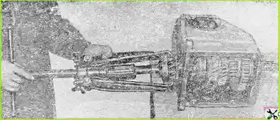
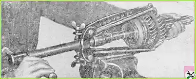
- 8. Turn the drive shaft so that the semicircular recess on its straight-toothed crown and on the cone is at the bottom, then remove the assembled drive shaft from the crankcase (Fig. 2)
- 9. Remove the ball bearing retaining ring.
- 10. Remove the gasket and the PTO hatch cover.
- 11. Remove the rear cover of the intermediate shaft and the thrust plate of the reverse axle.
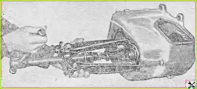
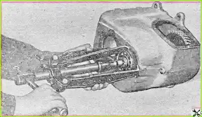
- 12. Remove the intermediate shaft ball bearing, having first pulled the shaft out of the crankcase (Fig. 3 and 4).
- 13. Remove the intermediate shaft with the inner ring assembly from the crankcase. Remove the inner ring of the roller bearing from the intermediate shaft.
- 14. Remove the outer ring of the intermediate shaft roller bearing from the crankcase. When disassembling and assembling the gearbox, keep in mind that the outer and inner rings of this bearing are not interchangeable. Therefore, if it is necessary to replace one of the rings, the entire bearing must be replaced.
- 15. Remove the reverse gear block axle.
- 16. Remove the reverse gear block from the crankcase.
- 17. Remove the intermediate shaft front bearing plug.
- 18. Remove the mud trap from the crankcase.
Disassembling the drive shaft
Remove the retaining ring, take out the thrust washer and the rollers of the front bearing of the driven shaft.
On some vehicles, the retaining ring and thrust washer are not installed.
The rollers of the front bearing of the driven shaft are not interchangeable.
They are sorted into groups by 0.005 mm and installed in the unit as a set only from one group, therefore, if one or more rollers are worn, the entire set must be replaced.
Punch and unscrew the ball bearing fastening nut and remove the bearing.
Disassembling the driven shaft
Remove the first gear and reverse gear from the shaft.
Punch and unscrew the synchronizer hub fastening nut.
Remove the hub and sliding sleeve of the synchronizer (Fig. 5).
Remove the crackers and synchronizer springs.
Remove sequentially: synchronizer locking ring, third gear pinion, spacer sleeve, thrust washer, second gear pinion
Disassembling the top cover
- 1. Remove the plug from the hole under the locking plunger.
- 2. Remove two pins from the cover neck.
- 3. Remove the conical spring.
- 4. Knock out the stoppers from the shift fork and the transfer head of the first and second gear rods.
- 5. Remove the fork and transfer head from the first and second gear shift rod and remove the rod.
- 6. Knock out the stopper of the third and fourth gear shift fork.
- 7. Remove the third and fourth gear shift fork from the rod, remove the rod and remove the locking pin from it.
- 8. Knock out the locking pins from the reverse fork and the reverse gear shift knob. Remove the reverse gear fork and shift knob assembly from the reverse gear shift rod and remove the rod.
- 9. Remove the locking springs, plungers and rod retainer balls from the cover holes.
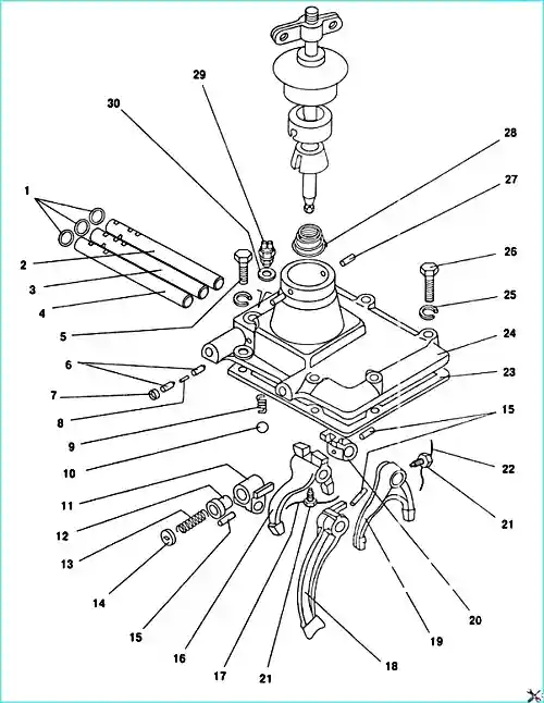
Gear shift mechanism: 1 - plug; 2 - first and second gear shift rod; 3 - third and fourth gear shift rod; 4 - reverse gear shift rod; 5 - M10x25 bolt; 6 - shift rod locking plunger; 7 - shift rod plunger hole plug; 8 - locking pin; 9 - Locking spring; 10 - Ball; 11 - Reverse gear rod head; 12 - Reverse gear safety switch; 13 - Reverse gear safety switch spring; 14 - Reverse gear safety switch spring stopper; 15 - Pin; 16 - Third and fourth gear shift fork; 17 - Cotter pin-wire; 18 - Reverse gear fork; 19 - First and second gear shift fork; 20 - First and second gear shift rod head; 21 - Shift fork screw; 22 - Cotter pin-wire of first and second gear fork locking screw; 23 - Top cover gasket; 24 - Top cover; 25 - Spring washer; 26 - Bolt; 27 - Pin; 28 - Shift lever cap; 29 - Reverse light switch; 30 - gasket
Disassembling the reverse gear rod transfer head. Punch and unscrew the spring stopper.
Remove the spring and fuse.
Determining the technical condition
Hold the parts of the disassembled gearbox (except for the bearings) in a cleaning solution and then wash them.
In parts with oil channels, thoroughly clean the latter.
After washing, carefully inspect the parts. replace parts with cracks.
If there are nicks, burrs and other irregularities on the machined surfaces, clean these irregularities to ensure good fit of the mating parts.
In this case, special attention should be paid to the condition and geometry of the seating surfaces under the bearings in the crankcase and on the shafts.
Carefully check the condition of the gear teeth of the gearbox.
Small cavities (pitting) are allowed on the working surface of the tooth, on an area of no more than 10% of the entire surface. Minor nicks, burrs on the ends of the teeth should be cleaned.
Chips on the working surface are not allowed. Inspect the condition of the splines in the splined connections and the grooves for the shift forks.
If there are any scoring, severe wear, crushing or chipping in the grooves for the forks and on the splines, the parts must be replaced.
Parts with stripped threads and worn surfaces for the oil seal must also be replaced.
Rinse the bearings in a clean solution and wipe with a cloth or blow with compressed air.
If the bearings are suitable for further operation, then, after drying them, lubricate them with the grease used for the gearbox and store them until they are needed.
Signs of defective bearings are:
- cracks, chips, scratches and chipping of metal on the balls (or rollers) and on the rolling races, increased radial clearance.
The values of permissible radial clearance are:
- - 0.05 mm for ball bearings;
- - 0.08 mm for intermediate shaft roller bearing.
The value of radial clearance in ball bearings is determined in the following way:
The bearing is installed so that its axis is horizontal. The ends of one of the rings, for example, the outer one, are fixed motionless.
Then move the free inner ring in the radial direction under a load of 10 kg.
In this case, the maximum radial clearance will appear in the upper part of the bearing between the ball and the surface of the rolling raceway.
To determine the clearance value, move the inner ring under the specified force in the opposite radial direction and measure the amount of movement with an indicator.
This method can be used to determine the radial clearance in the roller bearing of the intermediate shaft.
In the gearbox housing, the holes for the bearings of the drive and driven shafts, as well as for the bearings of the intermediate shaft, must be bored in one installation.
The distance from the axis of the holes for the bearings of the drive and driven shafts to the axis of the holes for the bearings of the intermediate shaft must be within 110.625 ± 0.07 mm.
The axis of the holes for the intermediate shaft bearings must be parallel to the axis of the holes for the bearings of the drive and driven shafts and lie in the same plane with it, the deviation must not exceed 0.04 mm over a length of 250 mm.
The distance from the axis of the holes for the intermediate shaft bearings to the axis of the holes for the axle of the reverse gear block must be within 71.25 ± 0.07 mm.
The axis of the holes for the axle of the reverse gear block must be parallel to the axis of the holes for the bearings of the drive and driven shafts and driven shafts and must lie in the same plane with them.
The deviation must not exceed 0.08 mm over a length of 200 mm.
The front and rear end planes of the crankcase must be perpendicular to the axis of the holes for the bearings of the drive and driven shafts. The deviation must not exceed 0.07 mm over a radius of 75 mm.
The inner ends of the eye for the reverse gear block must be perpendicular to the axis of the holes for the axis of the reverse gear block. The deviation should not exceed 0.1 mm on a radius of 21 mm.
Burrs and nicks on the gear teeth should be cleaned.
After assembling the synchronizer (when replacing the cone rings), it is necessary to process the cone surfaces of the rings so that the gap between the ends of the ring and the gear after grinding the cones is within 0.8-1.25 mm.
The lapping surface area should be at least 70% of the cone surface. The check should be carried out using a standard.
The gearbox gears should be selected so that the lateral clearance between the teeth is within 0.3-0.4 mm.
The 1st gear gear should be selected for the driven shaft so that the lateral clearance between the splines is no more than 0.18 mm.
The sliding clutch for switching 3rd and 4th gears must be selected with the hub.
In this case, easy movement of parts without noticeable lateral clearance should be ensured.
In the extreme positions of the sliding clutch for switching 3rd and 4th gears, corresponding to 3rd and 4th gears, longitudinal movement of the clutch within 0.2 mm is allowed.
")

")
")
")
")
")
")
")