Remove the valve covers
Turn out the spark plugs
We set the piston of the first cylinder to top dead center; to do this, close the hole for the spark plug of the first cylinder with your finger and turn the engine crankshaft with the starting handle until air begins to escape from under the finger. This will happen at the beginning of the compression stroke in the first cylinder.
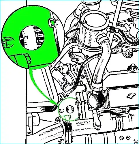
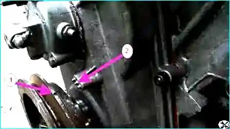
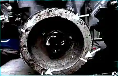
After making sure that compression has begun, carefully turn the engine crankshaft with the starting handle until the pointer on the clutch housing coincides with the ball cased into the flywheel (Figure 1), and for the GAZ-53 car - until the marks on the crankshaft pulley coincide with the central mark of the pointer V. m, t. (Fig. 2).
When the piston of the first cylinder is at TDC on the compression stroke, the intake and exhaust valves must be completely closed.
In this position, we set or check the gap between the rocker arm and the valve stem, which should be 0.25 - 030 mm on a cold (15 - 20 ˚ C) engine.
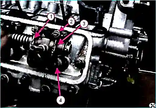
It is allowed to reduce the gap to 0.15-0.20 mm for valves located at the edges of the heads: the first and eighth inlet, the fourth and fifth exhaust (Fig. 3).
If the gap does not match: - loosen the lock nut of the adjusting bolt and, by rotating the adjusting bolt, set the required gap using the feeler gauge.
Tighten the locknut, holding the bolt from turning, and check the gap again.
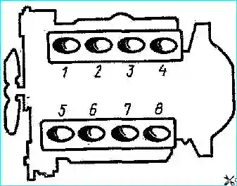
We adjust the clearances of the remaining cylinders in the order of operation of the cylinders 1-5-4-2-6-3-7-8, turning the crankshaft by ¼ turn when moving from cylinder to cylinder.
To better navigate and speed up the process, use quick-drying paint to mark the drive pulley into four parts (Figure 6).