Removing the master brake cylinder of the GAZ-53A must be done in the following sequence
Stop the engine and release the booster from the vacuum by pressing the brake pedal several times.
Disconnect the pipeline from the master cylinder coupling.
Displace the brake fluid from the master cylinder into the container by pressing the pedal several times.
Remove the rubber cap with the clamping ring from the end of the master cylinder.
Remove the brake pedal return spring. Remove the pin, pusher with rod and remove the protective cap with the clamping ring.
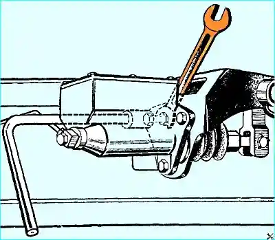
Remove the master cylinder from the pedal bracket. When unscrewing the bolts, it is recommended to use the key shown in Fig. 1.
Removing the master brake and clutch cylinder of the GAZ-66 vehicle must be performed in the following sequence.
Release the booster from the vacuum.
Disconnect the pipes from the clutches of the master cylinder.
Displace the liquid from the master cylinder into a container.
Remove the bracket of the master cylinder with the pedals in assembly.
Remove the rubber caps with clamping rings from the piston thrust cover.
Unscrew the nuts of the eccentric axles, remove the eccentric axles, remove the piston pushers with bushings (under the eccentric axles) and protective rubber caps from the cylinders.
Remove the cylinder from the pedal bracket.
Disassemble the master brake cylinder in the following sequence.
Clean the outer surface of the cylinder. Unscrew the filler plug with the gasket. Drain the brake fluid remaining in the cylinder and reservoir.
Remove the couplings with copper gaskets.
Remove the retaining ring, thrust washer (or remove the thrust cover with a gasket for GAZ-66), piston, cuff, spring with holder and valve from the cylinder.
To remove the parts, you can let compressed air into the cylinder through the outlet of the end of the cylinder.
Remove the master cylinder cover with a gasket.
Repair of master cylinder parts
Wash all master cylinder parts in pure alcohol and wipe with a clean napkin.
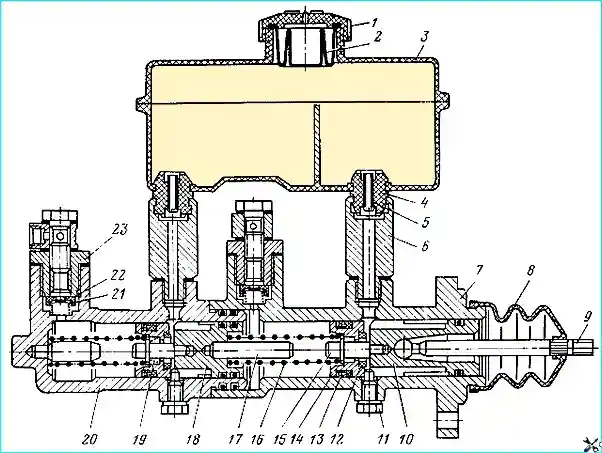
Master brake cylinder: 1 - reservoir cap; 2 - rubber boot; 3 - reservoir; 4 - rubber bushing; 5 - tube; 6 - nipple; 7 - primary cylinder casing; 8 - boot; 9 - pusher; 10, 18 - pistons; 11 - stroke limiter; 12 - seal; 15 - thrust rod; 16, 19 - springs; 20 - secondary cylinder casing; 21 - valve plate; 22 - valve
Check the wear of the parts and their condition.
The maximum permissible dimensions of the main cylinder parts are given in the table. 1.
Table 1
Nominal and repair dimensions of the main cylinder parts, mm:
Nominal size:
- - cylinder diameter 32.00+0.027 (32.08) ;
- - piston diameter 32.00-0.025 (31.85);
- - diameter of the edges of the working cuffs 33 ± 0.2 (32.75)
First repair:
- - cylinder diameter 32.25+0.027 ;
- - diameter piston 32.25-0.025 ;
- - diameter of the edges of the working cuffs 33.50 ± 0.2
Second repair:
- - cylinder diameter 32.50+0.027 ;
- - piston diameter 32.50 —0.025 ;
- - diameter of the edges of the working cuffs
Third repair:
- - cylinder diameter 32.75+0.027 ;
- - piston diameter 32.75-0.025 ;
- - diameter of edges of working cuffs 34.00 ± 0.2
Fourth repair:
- - cylinder diameter 33.00+0.027 ;
- - piston diameter 33.00-0.025 ;
- - diameter of edges of working cuffs -
Dimensions in brackets are permissible without repair
Master cylinder housing. Check for scoring and corrosion on the working surface of the cylinder. Clean
the bypass and outlet holes of the crankcase with a wooden stick, and the compensation hole with a soft blunt wire Ø 0.6 mm.
If there are signs of scoring, corrosion and wear on the surface of the cylinder, it is honed to a diameter of no more than 32.152 mm. In this case, new cuffs are installed.
If a leak appears after repair, then bore the cylinder and then hone it to one of the repair sizes. In this case, set the appropriate sizes of pistons and cuffs.
Master cylinder piston. Check for scoring, corrosion, wear, and clogged pistons bleed holes.
If the spring valve riveted to the front end of the piston is not securely seated or has shifted so that the piston holes are exposed, reinstall the valve and secure it with an additional punch.
Valve. Before washing, clean the valve with a blunt tool and immerse it in alcohol to flush. Replace it if there is any damage or swelling.
Carefully clean the cylinder filler plug from dirt and clean the vent hole.
The seals of the master cylinder piston must be elastic, and the working edges must be sharp and without defects.
Assembly, installation on a vehicle and testing of the master cylinder
Before assembly, wash all parts of the master cylinder in pure alcohol and blow them with compressed air. Lubricate the seals and the cylinder bore with brake fluid.
Assemble the master cylinder in the reverse order of disassembly.
After the spring with the valve and holder assembly, the inner seal and the piston are installed in the cylinder, check whether the piston returns well under the action of the spring.
After installing the washer and the retaining ring in the cylinder, check with a soft wire Ø 0.6 mm with a blunt end whether the compensation hole of the seal is blocked.
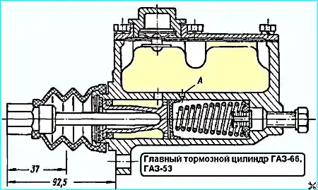
After assembling the master brake cylinder, the hole "A" with a diameter of 0.7 mm should not be blocked by the rubber seal (Fig. 3). This is checked with a wire with a diameter of 0.6 mm.
The distance from the crankcase mounting flange to the end of the pushrod should be 92.5 mm. The piston stroke should be no more than 37 mm (see Fig. 3).
After installing the cylinder on the pedal bracket, install the pusher with the cap assembly into the cylinder piston without putting the cap on the body.
Test the master cylinder, for this it is necessary:
- - install a hydraulic pressure gauge in the outlet;
- - fill the cylinder reservoir with brake fluid to the normal level. During and after testing, add fluid if necessary;
- - tighten the filler plug with the gasket;
- - bleed the cylinder by pressing the brake pedal 2-3 times, wipe the cylinder;
- - check the cylinder for leaks under a pressure of about 90 kg/cm². Create pressure by pressing the pedal with constant force.
There should be no fluid leakage, pressure drop, or pedal movement within 1.5 minutes;
- - check the cylinder valve for leaks, to do this, press the pedal and lower it.
Note the pressure gauge readings; the valve must maintain an excess pressure of 0.8 kg/cm² in the system for one hour;
- - disconnect the pressure gauge from the cylinder and attach the coupling with two new copper gaskets in its place using a bolt;
- - connect the pipeline to the coupling;
- - unscrew the filler plug and fill the brake fluid to the normal level;
- - tighten the plug with the gasket;
- - put the rubber cap on the cylinder casing and secure it with a clamping ring;
- - bleed the brake system.
When assembling the GAZ-66 master cylinder, take into account that the excess pressure valve is not installed in the cavity of the clutch master cylinder, and the pistons rest against the cover.
Replacing hydraulic drive parts
Before replace the part, clean and wash.
When replacing hose pipes or tees, tighten their connection securely.
The brake pipe is replaced if it is damaged, dented, or has a narrowed cross-section.
When bending the pipe to fit the place of its installation, be careful not to crack it.
To do this, put a spring sheath of the appropriate diameter on the pipe or bend the pipe using a roller.
The ends of the pipes must have double flanging to ensure tight connections.
When making new pipes, cut their ends strictly perpendicularly, preferably with a pipe cutter, so as not to crush them. Carefully clean the burrs on the ends along the outer and inner diameters.
Wash the inner walls of new brake pipes with pure alcohol.
Replace the flexible brake hose if scratches or other damage are found.
When replacing the brake hose, unscrew the connecting nut of the pipe suitable for it, then unscrew the nut securing the hose to the frame and then unscrew it from the wheel cylinder or tee on the rear axle.
Install the hose in the reverse order.
When tightening the nut securing the hose or the connecting nut of the pipe, hold the hose with a wrench to prevent it from turning.
The hose should not touch the parts chassis.
")

")
")
")
")
")
")
")