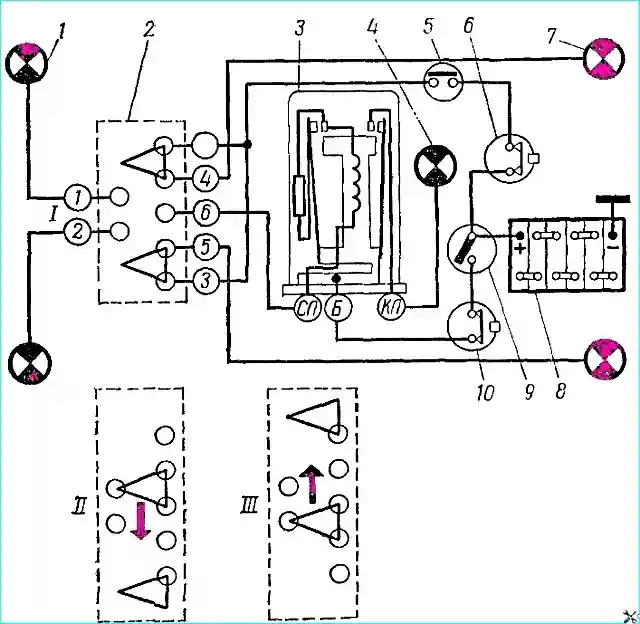
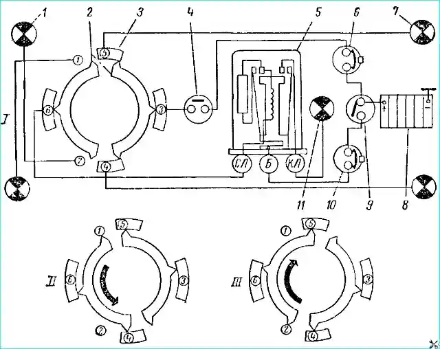
The turn signal switching diagrams are shown in Fig. 1 and 2.
The sidelights and taillights are switched on using a switch of the P105 type on the GAZ-53A vehicle and a P118 type on the GAZ-66 vehicle
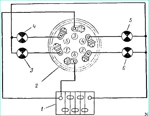
The operation of the switches is checked using test lamps according to the diagrams shown in Fig. 1 and 2.
When off, lamps 4 and 5 should light. When the right turn signal is on, lamps 4 and 6, and when the left turn signal is on, lamps 3 and 5.
If the switch on the GAZ-53A does not turn off after the car exits a turn, adjust the switch position.
To do this, loosen the two screws securing the switch to the bracket and move the switch until the rubber roller does not touch the steering wheel hub when the switch is in the off position (there should be a gap of 2 - 2.5 mm).
When the switch is turned on, the roller should be securely pressed against the wheel hub.
Every 25,000 km of vehicle mileage, lubricate the roller axle, lever axle and lever plate pressing the roller in the P105 switch.
The turn signals flash (70-100 flashes per minute). This is achieved by including a type RS57 interrupter in the electrical circuit of the turn signals.
Let's take a closer look at the design and operation of the turn signal lights:
The most widely used turn signals are those with an electromagnetic thermal current interrupter - RS57, RS57-V, designed for 12 V, and RS401 - for 21 V.
Turn signal device. A winding consisting of 50 turns of PEL wire with a diameter of 0.75 mm is placed on the steel core 9 (Fig. 3). The core is rigidly connected to bracket 11.
The breaker winding is connected in series with signal lamps 16 or 17, located in the rear light and sidelight, and when using the RS57V, also with control lamp 12, located on the instrument panel in the driver's cabin.
Steel anchors 4 and 10 are welded to the core
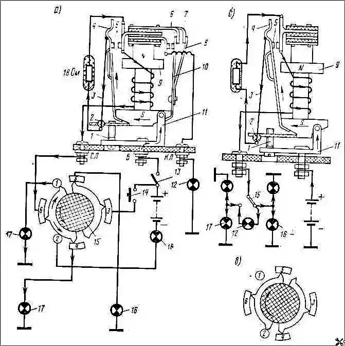
When not in use, contacts 5 are opened by the force of the stretched nichrome string 3, and contacts 6 are opened by the tension of the bronze plate 8. All contacts of the interrupter are silver.
The lower end of string 3 passes through glass bead 2 and is thickened by soldering. The bead isolates the string from the bracket.
The resistor has a resistance value of 18 Ohm and is made of a nichrome conductor.
Normal operation of the RS57 interrupter is ensured by simultaneously switching on two 21-light signal lamps, and the RS57-B has two 32-light signal lamps and one 1-light control lamp.
If one of the signal lamps burns out, the current decreases, resulting in a significant increase in the flashing frequency of the lamps, and in the circuit with the RS57 relay, the control lamp does not turn on.
Operation of the turn signal indicator
When the signal lamps are switched on, the current from the battery will flow through ignition switch 13, anchor 4, string 3, resistor, winding, switch 15 and to the lamps (see Fig. 3).
The current path in the diagram is indicated by arrows. The filament heating will be low.
The current passing through string 3 will cause it to heat up, as a result of which the string will lengthen and its tension will decrease.
At this time, steel anchor 4 will be attracted to the core of the electromagnet and contacts 5 of the interrupter will close.
Closed contacts 5 shunt resistor and string 3. The current in the lamp filament will increase and their filaments will glow at full incandescence.
Interruption of the current in the string is accompanied by its cooling and decrease in length.
The string will tighten again and open the contacts, after which the process is repeated. The contact vibration frequency is 60 ÷ 120 openings per minute.
Periodic closing and opening of the circuit of the control lamp 12 in the RS57 is ensured by the operation of contacts 6.
At the moment of closing of contacts 5, the current in the electromagnet winding increases, therefore the core is magnetized more strongly and, attracting the steel anchor 10, ensures the closing of contacts 6.
In this case, the control lamp is switched on at full voltage of the current source and glows at full heat.
After opening of contacts 5, due to the decrease in current in the electromagnet winding, the magnetization of its core decreases, and then, under the action of the elastic bronze plate 8, contacts 6 will open and turn off the control lamp circuit.
The electrical circuit of the control lamp in the RS57-V is closed through two unlit lamps.
Since the control lamp has a high resistance, the current in the circuit of the signal lamps connected in series with the control lamp will be small and the glow of the filaments of the signal lamps will be practically unnoticeable.
The control lamp has a low power, and therefore its operation will be normal. The electric circuit of the lamps is switched on only when the ignition switch 13 is on.
Device of the turn signal switch
The circuit of the turn signal lamps is switched on by switch P118 (GAZ-66), P105 (ZIL-130, etc.)
In Fig. 3, a and b show the diagram of the position of the two contact plates of the rotor of the P118 switch when the car is turning left and right.
In the neutral position of the switch handle, the right contact plate of the rotor closes terminals 5 and 4, which allows the brake light lamps to be turned on when the brake light switch 14 is turned on.
The turn signal is most often turned off mechanically using conventional switches.
On most cars, the turn signal is automatically turned off by special devices when the steering wheel is set to its original position after turning the car.
On cars of the Minsk and Kremenchug plants, where 24-volt equipment is used, an electromagnetic current interrupter RS-401, made on the basis of RS57, is installed.
In these interrupters, the cross-section and number of turns of the winding are changed, the resistor has a resistance value of 38 Ohms, and for to reduce oxidation of the main contacts, a capacitor with a capacity of 105 pF is connected in parallel to them.
Main faults of the turn signal.
The following faults most often occur:
- - violation of the current interrupter adjustment, which causes a change in the frequency of the light "flashing" and even welding of the contacts;
- - burnout of string 3 (see Fig. 3), which occurs when it is strongly tensioned and the generator voltage increases above the set value:
- - burnout of one of the signal lamps, which causes, depending on the degree of tension of the string, either very frequent "blinking" of the switched-on lamp, or cessation of vibration of the breaker contacts.
Check diagram of the P105 turn signal switch of the GAZ-53A vehicle
Check diagram of the turn signal switch P118 of the GAZ-66 vehicle
Adjustment of electromagnetic current breakers
The current breakers are adjusted as needed with screw 1 (see Fig. 3).
Tightening the screw increases the tension of string 3, as well as the gap between contacts 5, the gap between anchor 4 and core 9, after which the opening of contacts 5 is accelerated, and at the same time the frequency of lamp flashing increases.
To reduce the frequency of lamp flashing, screw 1 is unscrewed.
By bending brass strip 7, the tension of spring plate 3 is adjusted, and at the same time the operation of the control lamp changes.
The operation of the direction indicators is checked using a control lamp.
If the filament of the lamp in the sidelight or rear light burns out, the frequency of flashing of the control lamp increases sharply. If damaged, replace the breaker.
")

")
")
")
")
")
")
")