When installing the flywheel, its mounting nuts must be tightened uniformly with a force of 7.6-8.3 kgm
The runout of the flywheel friction plane is no more than 0.15 mm at a radius of 165 mm.
If the runout exceeds 0.15 mm, the unit must be disassembled.
The bearing of the guide end of the gearbox input shaft must be filled with UTV 1-13 grease and installed in the crankshaft socket using a special mandrel.
When installing the clutch, the axis of the driven disk must be aligned with the axis of the crankshaft.
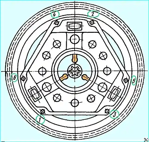
The bolts securing the clutch housing to the flywheel must be tightened evenly in the order shown in Fig. 1.
The tightening torque of the bolts should be within 2-3 kgm.
The crankshaft assembly with the flywheel and clutch must be subjected to dynamic balancing.
Before balancing, check the freedom and ease of rotation of the disk by disengaging the clutch and moving the tension levers by 11.7 mm.
In this case, the size from the working surface of the flywheel to the upper heads of the tension levers should be within 53-54.5 mm.
If the disk does not rotate freely, as well as if there is a deviation in size, the unit must be disassembled.
Before balancing, fill the internal cavities of the crankshaft with spindle oil, put a balancing weight of 2237 g on each crank pin on the crankpins.
Permissible imbalance is 70 gsm.
Imbalance shall be eliminated by drilling the metal on the outer diameter of the flywheel with a drill of 8 mm in diameter to a depth of no more than 10 mm, maintaining a distance between drillings of no less than 11 mm.
Balancing shall be performed with an initial imbalance of no more than 180 gsm. In case of greater imbalance, the unit must be disassembled.
Before installing the crankshaft in the cylinder block, all mating surfaces must be thoroughly wiped.
The oil channels of the crankshaft and block must be blown out with compressed air.
The main bearing shells must be lubricated with engine oil.
The size of the main bearing shells must correspond to the size of the crankshaft main journals.
The tightening torque of the nuts of the studs for fastening the main bearing caps must be 11-12 kgm.
The axial clearance of the crankshaft, measured between the front washer of the thrust bearing and the steel thrust washer, must be within 0.075-0.175 mm.
The axial clearance is adjusted by selecting the rear washer of the thrust bearing.
The nominal and repair dimensions of the front and rear washers of the thrust bearing are given in the table. 1.
*Table 1*
Nominal and repair sizes of the front and rear washers of the thrust bearing
Nominal size:
- - thickness of the front washer 2.35-2.45 mm;
- - thickness of the rear washer - 2.45-2.50 mm
First repair:
- - thickness of the front washer 2.35-2.45 mm;
- - thickness of the rear washer - 2.65-2.70 mm
Second repair:
- - thickness of the front washer 2.35-2.45 mm;
- - thickness of the rear washer - 2.85-2.90 mm
When the main bearings are fully tightened, the crankshaft should be able to turn freely by hand on the flywheel.
")

")
")
")
")
")
")
")