
")
")
")
")
")
Fuel tank of a Gazelle car
If the seal of the fuel tank is damaged, it should be removed from the vehicle
To do this, it is necessary to loosen the nuts securing the hinge plate of the filler pipe hatch and remove bracket 3, remove the body floor hatch (above the fuel tank) and disconnect the fuel hoses from the fuel intake, remove the wires going to the fuel level indicator sensor and insulate them, disconnect from brackets, tightening straps (after placing stops under the tank) and remove the tank.

Before checking the tightness of the fuel tank, remove the fuel level indicator sensor and the fuel intake with filter by unscrewing five screws each securing their flanges to the tank; remove the filler pipe together with hoses (for vans and buses).
The tightness of the fuel tank is checked with compressed air under a pressure of 20 kPa (0.2 kgf/cm 2), placing it in water, having previously closed all flanges and holes with plugs or plugs.
Air is supplied through a special tube inserted into the filling pipe and equipped with a valve to shut off the access of air when the pressure rises above 20 kPa (0.2 kgf/cm 2) and a control pressure gauge.
Air bubbles will escape in areas of leakage. These places should be marked with paint.
You can solder the tank only after thoroughly washing it (inside and outside) with hot water and blowing it with compressed air. After soldering, you should check the tank for tightness again.
Assembly and installation of the fuel tank is performed in the reverse order of disassembling and removing the tank from the vehicle.
During assembly, it is necessary to ensure that the gaskets under the flanges of the intake pipe and the level indicator sensor are intact and correctly installed. To prevent fuel from leaking through thread leaks, it is recommended to dip the flange mounting screws in red lead or shellac before tightening.
To avoid depressurization after assembling and installing it on the car, all connections of the tank must be tightened tightly, but without much effort.
Faulty fuel line parts should be replaced with new ones.
Fuel pump of ZMZ-402 engine
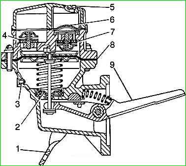
The fuel pump requires repair in cases of diaphragm breakthrough, leakage of suction or exhaust valves, loss of elasticity of the diaphragm rod seal, as well as wear of the drive lever and textolite washer of the diaphragm rod.
Disassemble the fuel pump in the following order:
- - unscrew two screws 5 securing the cover and carefully remove the cover, rubber sealing gasket and pump strainer;
- - unscrew the eight screws securing the pump head to the body, carefully remove the head and release the diaphragm;
- - if it is necessary to replace the valves, press the valve races out of the pump head, remove the rubber valve, valve plate and spring from the race.
It is not recommended to unnecessarily unscrew the fuel inlet and outlet fittings from the pump head and cover;
- - unscrew the threaded plugs of the lever axis from the body;
- - remove the lever axis, having first removed the lever spring;
- - remove the pump drive lever and the lever bushing;
- - remove the diaphragm along with the rod, spring, seal and seal holder from the pump housing;
- - remove the manual drive lever shaft together with the rubber sealing ring, having first released the lever spring;
- - disassemble the diaphragm, to do this, press out the spring and, removing the steel seal holder, remove it;
- - unscrew the rod nut, remove the spring washer, upper cup, diaphragm blades, lower cup and sealing washer.
Inspection and control of pump parts
Carefully inspect the condition of the parts, first cleaning and rinsing them in kerosene or unleaded gasoline. If it is necessary to replace the valve, pay special attention to the condition of the seat in the head.
Replace rubber valves, head cover gaskets or diaphragm blades that are warped and lose elasticity.
Total wear of the working surface of the lever, about The holes of the lever, bushing, axle and pump body, as well as the textolite washer of the diaphragm thrust are considered acceptable within limits that ensure a pump flow of at least 145 l/h at an eccentric rotation speed of 1800 min -1.
Pump assembly
The pump is assembled in the reverse order of disassembly. In this case, special attention should be paid to the correct subassembly of the diaphragm and its installation in the pump.
Before assembly, it is necessary to check the characteristics of the pump spring: the free length of the spring is 50 mm; with a load of 50+3 N (5.1+0.3 kgf), the spring length should be 28.5 mm.
The number of spring turns is 6+0.5, the outer diameter of the spring is 24 mm, the wire diameter is (1.80.03) mm, the material is 65GA steel.
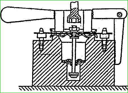
It is recommended to perform subassembly of the diaphragm in a special device.
Before assembly, wash all parts in clean gasoline, soak the diaphragm blades for 30-40 minutes in kerosene and wipe with a clean cloth on both sides.
Then insert the rod into the device and sequentially put on the protruding end of the rod the rubber seal of the rod, a sealing copper washer, the lower cup (concave side down), four diaphragm blades (so that the pins of the device fit into its hole), the upper cup and screw hand nut onto several threads, placing a spring washer under it.
Then clamp all the parts in the fixture and tighten the nut all the way.
Remove the assembled diaphragm from the device, put the spring on the rod and release the rubber seal from the spring.
Press the spring and install the steel holder on the rubber seal.
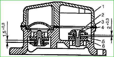
When pressing valve races into the pump head, it is necessary to ensure the dimensions between the valve plate and the race for the inlet valves are 1.5-1.8 mm, for the discharge valves - 2.0-2.3 mm.
When assembling a fully assembled diaphragm (with seal and spring, with head and body), you should first lightly tighten the eight screws securing the head to the body, and then, moving the manual drive lever to its highest position, tighten them completely.
This will prevent the diaphragm from bursting or overdrawing when the pump starts.
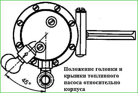
When assembling the pump, the head and cover must be placed relative to the body in the position shown in Figure 5.
After assembly, you should check the pump for the start of flow, pressure, vacuum and flow as indicated above.
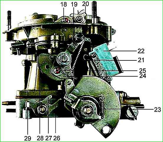
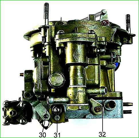
Carburetor K-151
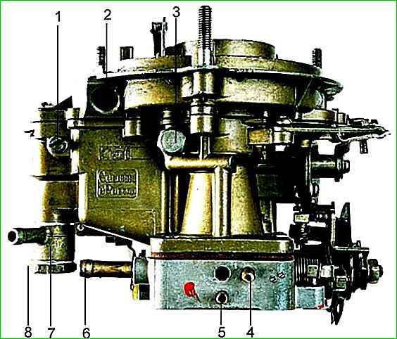
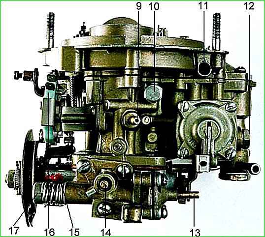
Disassembly of the carburetor is recommended to be performed in the following order:
- - unscrew the screw securing the air damper rod to the drive lever;
- - unscrew the seven screws securing the float chamber cover, remove the cover and the gasket under it, being careful not to damage the gasket;
- - unscrew the two screws and remove the air damper if the gaps between the air damper and the air pipe exceed normal;
- - unscrew the screw and remove the accelerator pump nozzle;
- - unscrew the screw and remove the econostat sprayer;
- - unscrew the plug and remove the float axis, remove the float, remove the fuel valve needle. Unscrew the fuel valve body together with the gasket;
- - unscrew the filter plug and remove the mesh filter;
- - unscrew the four screws securing the accelerator pump diaphragm cover, remove the cover and remove the diaphragm with the spring;
- - unscrew the main jets of the first and second carburetor chambers;
- - unscrew the air jets and remove the emulsion tubes of the first and second chambers;
- - unscrew the idle system jets of the first chamber and the transition system jets;
- - unscrew the two screws and remove the diaphragm locking device of the forced idle economizer;
- - unscrew the three screws and remove the housing of the autonomous system.
Control and inspection of carburetor parts
After disassembly, you should rinse the parts in gasoline, blow them with compressed air and check their technical condition, which must meet the following requirements:
- - all parts must be clean, free of soot and resinous deposits;
- - the jets, after washing and blowing with compressed air, must have a given capacity or size;
- - all valves must be sealed, gaskets must be intact and have traces (prints) of the sealing planes;
- - there should be no noticeable wear (play) in the connections: float axis - float bracket, mixing chamber housing bosses - throttle valve axis.
Assembling the carburetor is carried out in the reverse order of disassembly.
First you need to assemble all three parts of the carburetor - the cover, float and mixing chamber housings, and then connect them together. When assembling you need:
- - ensure the safety and correct installation of gaskets;
- - make sure that the throttle and air dampers turn completely freely, without jamming and tightly cover their channels;
- - tighten all threaded connections tightly, but without excessive force;
- - check and, if necessary, adjust the fuel level in the float chamber.