Engine fuel supply equipment - split type
It consists of a high-pressure fuel pump with an all-mode speed controller and a built-in corrector for adjusting the fuel supply, a fuel priming pump, injectors, coarse and fine fuel filters, low and high pressure fuel lines.
From the tank, through the coarse filter, the fuel is sucked in by the fuel priming pump and fed to the fine filter and then to the high-pressure fuel pump.
According to the firing order of the cylinders, the fuel pump delivers fuel through the high pressure fuel lines to the injectors, which atomize it in the engine cylinders.
Through the bypass valve in the fuel pump and the jet in the fine filter, excess fuel, and with it the air that has entered the system, is discharged through the fuel line to the fuel tank.
The fuel that has leaked into the cavity of the nozzle spring is discharged through the drain pipe to the tank.
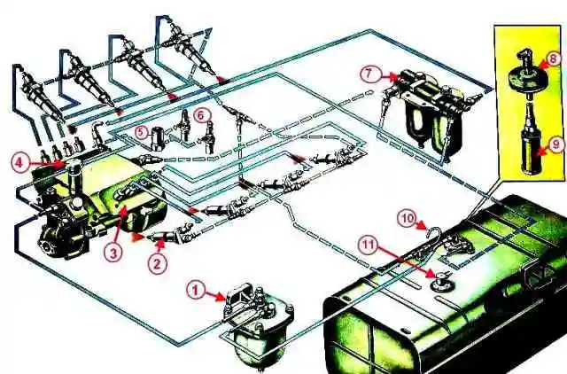
Scheme of the power supply system: 1 - coarse fuel filter; 2 - nozzle; 3 - high pressure fuel pump, 4 - manual fuel priming pump, 5 - solenoid valve; 6 - EFU candle, 7 - fine filter; 8 - a reception pipe of a tank; 9 - tank filter; 10 - fuel tank breather; 11 - fuel gauge sensor
High pressure fuel pump
The pump is located in the collapse of the engine between the rows of cylinders and has a gear drive.
The high-pressure fuel pump is eight-section, according to the number of engine cylinders.
The engines are equipped with high-pressure fuel pumps of various models, which have design and adjustment differences (see the article "Specifications").
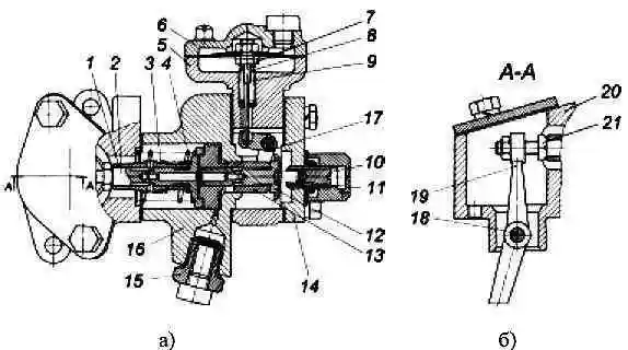
Model 173 High Pressure Fuel Pump
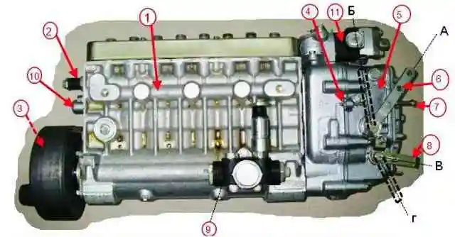
Model 173 injection pump: 1 - fuel pump housing; 2 - bypass valve; 3 - damper clutch; 4 - bolt for limiting maximum speed; 5 - speed controller; 6 - regulator control lever; 7 - a bolt of restriction of the minimum turns; 8 - stop bracket; 9 - fuel priming pump; 10 - starting feed adjustment bolt; 11 - boost fuel supply corrector; A - the position of the lever at the minimum idle speed; B - lever position at maximum idle speed; B - the position of the bracket during operation; G - the position of the bracket when the feed is off
The fuel pump assembly is shown in fig. 2.
With a high-pressure fuel pump, the speed controller 5, the fuel priming pump 9 and the damper coupling 3 are combined in one unit.
Design and operation of the high pressure fuel pump
The high-pressure fuel pump consists of sections, separate pumping elements located in a common housing.
The number of sections is equal to the number of engine cylinders.
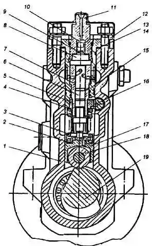
Model 173 high pressure fuel pump section: 1 - pump housing; 2 - lower pusher plate; 3 - pusher spring; 4 - upper pusher plate; 5 - rotary sleeve; 6 - plunger; 7 - plunger bushing; 8 - discharge valve seat; 9 - discharge valve; 10 - valve stop; 11 - fitting; 12 - pressure flange; 13.14 - gaskets; 15 - section body; 18 - rail; 17 - pusher; 18 - pusher roller; 19 - camshaft
The arrangement of the high pressure pump section is shown in fig. 3.
In the casing 1 of the pump, casings of sections 15 with plunger pairs, discharge valves and fittings 11 are installed, to which high-pressure fuel lines are connected.
Discharge valve 9 and valve seat 8, as well as plunger 6 with sleeve 7 are precision pairs that can only be replaced as a set.
The plunger sleeve is locked in a certain position by a pin pressed into the section body.
The plunger 6 is driven by the camshaft 19 through the roller pusher 17. The spring 3 through the lower plate 2 constantly presses the pusher roller against the cam
The pushers, having flats on the side surfaces, are held from turning by clamps pressed into the pump housing.
The design of the plunger pair allows you to dose the fuel by changing the start and end points feed,
To change the amount and moment of the start of the fuel supply, the plunger in the sleeve is rotated by the rotary sleeve 5 (Fig. 3), which engages with the rail 16.
Adjustment of the uniformity of the fuel supply at the maximum mode by each section of the pump is carried out by turning the section housing with the sections fastening nuts loosened.
Changing the geometric start of injection depending on the amount of feed (engine load) is provided by control edges made on the end of the plunger.
The section works as follows
When the plunger 6 moves down under the action of the spring 3, fuel under slight pressure created by the fuel priming pump enters the space above the plunger through the longitudinal channel in the housing.
When the plunger moves upwards, fuel enters the high-pressure fuel line through the delivery valve and is bypassed into the fuel supply channel until the end edge of the plunger closes the bushing inlet.
With further upward movement of the plunger, the pressure in the space above the plunger increases sharply.
When the pressure reaches such a value that it exceeds the force created by the injector spring, the injector needle will rise and the process of injecting fuel into the engine cylinder will begin.
As the plunger moves further upwards, the cut-off edges of the plunger open cut-off holes in the bushing, which causes a sharp drop in fuel pressure in the discharge line, the injector needle landing on the atomizer locking cone and stopping the fuel supply to the combustion chamber.
On the inner surface of the sleeve 7 of the plunger there is an annular groove, and in the wall there is a hole for draining fuel that has leaked through the gap in the plunger pair.
The seal between the plunger sleeve and the section housing, the section housing and the pump housing is carried out by rubber rings.
From the cavity around the plunger sleeve, the leaked fuel enters through the groove on the plunger sleeve into the low pressure cavity of the pump housing and then through the bypass valve and pipeline to the fuel tank.
The camshaft is located at the bottom of the fuel pump housing.
The camshaft rotates in tapered roller bearings and an intermediate support.
The camshaft is installed with an interference of 0.01-0.07 mm, which is provided by adjusting and gaskets installed between the bearing cover and the pump housing.
The sections are connected to the pump speed controller via a rail.
The fuel pump rail moves in guide bushings pressed into the pump housing. At the end of the rail protruding from the pump, there is a bolt 10 (Fig. 2), with which it rests against the protective cap when the rail is in position before starting the engine.
When the bolt is removed from the rack, the starting feed is reduced.
The lubrication of the fuel pump is centralized, from the engine oil system. The oil is supplied to the corrector by boost, from where, merging into the cavity of the regulator, it enters the cavity of the camshaft of the pump.
Speed controller
The speed controller 5 (Fig. 2) is a mechanical all-mode direct action with an overdrive gear for the load drive, designed to maintain the engine speed set by the driver by automatically changing the amount of fuel supplied depending on the change in engine load.
In addition, the governor limits the maximum engine speed and keeps the engine idling.
The regulator has a device for turning off the fuel supply at any time, regardless of the engine operating mode. By automatically maintaining the speed mode under changing loads, the governor ensures economical operation of the engine.
The device of the speed controller is shown in fig. 4.
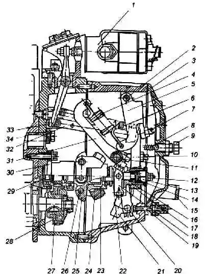
Rotational speed regulator: 1 - boost fuel supply corrector; 2 - axis of the two-arm lever; 3 - cover of the inspection hatch; 4 - regulator spring; 5 - two-arm lever; 6 - rack lever spring; 7 - two-arm lever screw; 8 - buffer spring; 9 - buffer spring housing; 10 - adjusting bolt; 11 - spring lever shaft; 12 - negative corrector; 13 - corrector spring housing; 4 - negative corrector spring; 15 - backstage bracket; 16 - negative corrector bushing; 17- regulator lever; 18 - negative corrector lever; 19 - power adjustment screw; 20 - rail lever; 21 - wings; 22 - heel; 23 - cargo clutch; 24 - regulator weights; 25 - holder of goods; 26 - cargo axis; 27 - drive gear; 28 - crackers; 29 - roller holder loads; 30 - glass; 31 - spring lever; 32 - rack rod; 33 - rail; 34 - emphasis
The regulator is located on the rear end of the high pressure fuel pump.
On a cone to the claw shaft is the drive gear 27 with a damping device.
The rotation from the pump shaft to the drive gear is transmitted through rubber crackers 28.
The driven gear is made as one piece with the shaft 29 of the load holder and is mounted on two bearings in the cup 30.
A weight holder 25 is pressed onto the roller (Fig. 4), on the axes 26 of which there are weights 24.
The weights with their rollers rest against the end of the clutch 23, which, through the thrust bearing and the heel 22, transmits the force of the weights to the regulator lever 17, suspended together with the two-arm lever 5 on the common axis 2.
The clutch 23 with the thrust heel 22 in the assembly rests at one end on the guide surface of the holder, and at the other end is suspended on the lever 18 of the negative corrector, fixed on the sleeve 16 of the negative corrector.
The heel of the weight coupling is connected through the negative corrector assembly with the rail lever 20 and through the rod 32 with the fuel pump rail.
The rack lever spring 6 is attached to the top of the rack lever, holding the pump rack in the position corresponding to the maximum flow, which provides increased fuel supply when starting the engine.
A finger is pressed into the lower part of the rack lever, which enters the hole of the backstage slider 21.
The shaft 11 of the regulator lever is rigidly connected to the control lever 6 (Fig. 2) and the spring lever 31 (Fig. 4).
The movement of the regulator control lever is limited by two bolts 4 and 7 (Fig. 2).
At the spring lever 31 (with a short hook) (Fig. 4) and the two-arm lever 5 (with a long hook), the regulator spring 4 is hooked, the force of which is transmitted from the two-arm lever to the regulator lever through the screw - 7 of the two-arm lever.
Adjusting bolt 10 is screwed into the regulator lever, which rests against the shaft of the spring lever and serves to adjust the nominal fuel supply.
In the lower part of the regulator lever there is a corrective device (12,13,14,16,18) with a negative corrector, designed to form the external speed characteristic of the injection pump and the engine torque.
The regulator lever is equipped with a side pad that holds the sleeve 16 of the reverse corrector and the thrust heel 22 from rotation.
In addition, the shank of the side cover bolt, entering the side longitudinal groove of the sleeve, prevents it from falling out of the lever bore.
The stop 34, fixed on the body of the regulator, prevents the spring arm 31 from dangerously approaching rotating loads. To completely turn off the fuel supply, a stop mechanism is used, consisting of a backstage 21, a bracket 15 and a return spring.
During operation, the link is pressed against the adjusting screw 19 by the force of the return spring.
At the back, the regulator cover is closed by a cover 3 of an inspection hatch with a buffer device consisting of a body 9 and a spring 8, which, by smoothing the vibrations of the regulator lever 17, ensures stable operation of the engine at idle.
The principle of operation of the speed controller is based on the interaction of the centrifugal forces of the weights and the forces of the springs with different pre-strain.
When the engine is not running, the regulator weights are in the reduced position, and the rail 33 under the action of the spring 6 of the rail lever is in the maximum feed position (leftmost position).
When starting the engine, when the crankshaft speed reaches 460-500 min -1 (the control lever rests against the minimum speed limit bolt), the governor weights, under the action of centrifugal force, overcome the resistance of the rack lever spring and shift the lever of the rack 32 through the clutch of loads 23 until the bushing 16 of the negative corrector stops in the regulator lever.
Further, overcoming the resistance of the buffer spring 8, the weights move the entire system of levers and the injection pump rail to the right until the cyclic feed of the injection pump section is established, corresponding to the minimum speed mode (minimum idle speed mode).
When you press the control pedal, the regulator control lever and the spring lever 31 rigidly connected to it rotate at a certain angle, which leads to an increase in the tension of the regulator spring.
Under the influence of the spring, the lever 17 of the regulator moves the lever system, the weight clutch and the rail in the direction of increasing the feed, and the engine speed increases.
This happens until the centrifugal force of the weights balances the tension force of the spring 4, i.e. to a steady state of engine operation.
Thus, each position of the governor control lever corresponds to a certain number of engine revolutions.
When the total moment of resistance to the movement of the car decreases, the engine speed increases. In this case, the centrifugal force of the loads increases.
The weights diverge and, overcoming the force of the regulator spring, move the weight clutch 23 and the heel 22.
In this case, the lever system and the rail move in the direction of decreasing feed (to the right) until the number of engine revolutions given by the position of the control lever, i.e. until there is an equilibrium between the centrifugal force of the weights and the spring force of the regulator.
With an increase in the total moment of resistance to the movement of the car, the crankshaft speed decreases, therefore, the centrifugal force of the regulator weights also decreases.
With the force of the spring 4 of the regulator, the lever system, the heel and the weight clutch will move to the left and move the rail to the left, in the direction of increasing the feed.
The delivery of fuel in sections increases until the engine speed reaches the value set by the position of the governor control lever.
The engine is stopped by turning the link bracket 15 down. In this case, the link 21 and the lower end of the lever 20 of the rail turn to the left, the pump rail extends to its extreme position, and the fuel supply stops.
The negative corrector (12, 13, 14, 16, 18) provides a gradual decrease in the cyclic fuel supply when the pump camshaft speed is reduced to 500 min -1 and thus ensures smokeless engine operation.< /p>
At a crankshaft speed corresponding to the nominal one, the centrifugal force of the weights exceeds the preload force of the corrector spring 14, and the heel rests against the main regulator lever through the corrector 12 and sleeve 16.
When the frequency of rotation of the camshaft of the high-pressure fuel pump is reduced, the force of the corrector spring becomes sufficient to overcome the force of the loads.
At the same time, the corrector 12 moves out of the sleeve 16 and, moving the weight clutch and the lever system, shifts the injection pump rail in the direction of reducing the cyclic fuel supply.
The frequency of rotation of the camshaft, corresponding to the moment the corrector starts working, i.e. the moment of the beginning of the extension of the corrector from the sleeve, is regulated by the pre-compression of the spring 14.
The lower the speed, the greater the amount of protrusion of the corrector from the sleeve and the greater the value of the restriction of cyclic fuel supply.
At 500 min-1, the value of the cyclic fuel supply limitation is the largest, its value is determined by the maximum value of the corrector protrusion.
The speed controller is equipped with a fuel boost corrector 1 to reduce the heat density and smoke in diesel exhaust gases at low speeds and transient conditions.
In addition, the corrector protects the engine in emergency situations that occur when the turbocharging system fails.
The principle of operation of the boost corrector is that when the boost air pressure decreases, it acts on the fuel pump rail, reducing the fuel supply.
Corrector for boost fuel supply: a) - horizontal section; b) - vertical section; 1 - stop sleeve; 2 - emphasis; 3 - sleeve spring; 4 - piston spring; 5 - membrane body; 6 - membrane cover; 7 - locknut of the membrane rod; 8 - spring; 9 - rod with a membrane; 10 - corrector spring housing; 11 - corrector spring; 12 - spool; 13 - piston; 14 - corrector cover; 15 - oil supply fitting; 16 - corrector body; 17 - lever; 18 - lever axis; 19 - lever; 20 - spacer; 21 - lever adjusting bolt
The boost corrector (fig. 5) is mounted on the top of the regulator housing. The corrector housing 16, the membrane housing 5 and the corrector cover 14 are attached to the spacer 20 with bolts.
Inside the body of the corrector, there is a pair of piston 13 and spool 12. Through stop 2, the piston is pressed by spring 4 to the body of the corrector.
A stop sleeve 1 is installed on the stop, which is constantly pressed against the adjusting bolt 21 of the lever 19 by the spring 3.
The lever is mounted on axle 18 in a spacer.
At one end of the lever there is an adjusting bolt with a nut, and the other end, when the corrector is working, directly acts on the injection pump rail.
In the membrane housing there is a membrane made of a special fabric, assembled with a stem 9, closed with a cover 6.
The cover has a hole for air supply from the engine intake manifold.
The lever 17, mounted on the axis, serves to transfer the movement from the stem to the spool 12.
The corrector spring 11 rests against the spool.
To change its pre-compression, a spring body 10 is screwed into the cover 14 of the corrector.
A lock nut and a cap are screwed onto the body.
The fitting 15 for supplying oil from the engine lubrication system is screwed into the body of the corrector.
The mating parts of the boost corrector are sealed using paronite gaskets.
When the engine is not running, there is no oil pressure in the lubrication system and air in the intake correctors.
Spring 4 presses piston 13 with stop 2 to corrector body 16.
Correct spring ra 11 presses the spool 12 and the stem 9 with the membrane until it stops against the membrane cover.
When the engine is started, oil from the engine lubrication system through the screw 15 begins to flow into the piston cavity of the corrector and through the open drain windows of the piston, axial channels of the spool, piston and stop merges into the cavity of the regulator.
When the engine enters the idle mode, the high-pressure fuel pump rail moves from the starting position to the side of the feed reduction.
Following the rail under the action of spring 3, the sleeve 1 moves, turning the lever 19.
The movement of the sleeve relative to the stop leads to the overlap of the drain windows of the stop, as a result of which the free drain stops, the oil pressure in the under-piston cavity increases; and the piston starts to move to the left to its working position.
The movement of the piston continues until the opening of the drain windows of the piston by the end working edge of the spool.
When the engine is running under load and the crankshaft speed increases, the air pressure in the membrane cavity increases.
The membrane is deformed, the rod moves the corrector lever 17, which in turn shifts the corrector spool to the right.
At the same time, the flow area through which oil flows from the under-piston cavity to the axial channel of the piston increases, the oil pressure in the under-piston cavity decreases, and the piston, together with the stop, moves to the right under the action of the spring, restoring its position relative to the spool.
Following the piston and stop under the action of the starting spring, the injection pump rail moves.
Thus, an increase in air pressure in the membrane cavity leads to an increase in the cyclic fuel supply.
The movement of the rail is accompanied by the rotation of the lever 19, while the amount of movement of the rail and the change in the cyclic feed is determined by the amount of movement of the piston and stop.
When the crankshaft speed decreases, the pressure of the turbocharger drops, the pressure in the membrane cavity decreases, the spool 12 moves to the left under the action of the spring 11 and the working edge of the end surface of the spool blocks the drain windows of the piston.
In the under-piston cavity, the oil pressure increases, the piston moves to the left until the drain windows open, and through stop 2 and lever 19 shifts the rail in the direction of decreasing feed.
Thus, a change in air pressure in the membrane cavity leads to a change in the position of the spool, the piston automatically tracks the position of the spool and ensures the corresponding movement of the injection pump rack.
The amount of rack movement and the change in the cyclic feed is determined by the pressure drop in the membrane cavity and the characteristics of the corrector spring.
With an increase in inflation pressure of about 0.06 MPa (0.6 kgf / cm 2), the feed restriction by the corrector is removed.
When the engine is stopped, the corrector automatically switches on the starting feed.
Dismantling the boost corrector together with spacer 20 in operation is not recommended, since then the lever 19 may be incorrectly installed relative to the rail, leading to engine spacing.
If it is necessary to dismantle (for example, during repair), during the subsequent installation of the corrector on the regulator, move the pump rail to the off-feed position with the stop link bracket and insert the corrector with a spacer into the regulator body.
Then release the backstage bracket. After that, it is necessary to check the adjustment of the boost corrector, as well as check the regulator to turn off the fuel supply.
Basic adjustments provided by the design of the regulator
- The minimum idle speed is regulated by bolt 7 (Fig. 2) and buffer spring housing 9 (Fig. 4);
- The maximum idle speed (the beginning of the rack ejection) is regulated by bolt 4 (Fig. 2).
- Rated power (feed) is adjusted by bolt 10, adjusted by screw 19 (Fig. 4).
- The pretension of the spring (the difference between the revolutions of the end and the beginning of the ejection of the rack) is adjusted by screw 7 (Fig. 4).
- Fuel supply at 500 min -1 is regulated by reverse corrector nut 12 (Fig. 4):
- The pretension of the reverse corrector spring (the speed at which the corrector starts to operate) is regulated by the corrector body 13 (Fig. 4).
The adjustment features include the fact that in order to ensure a reduced force on the control lever, the spring lever, when adjusting the speed of the start of the regulator, should be as close as possible to the stop in the regulator body, which limits its rotation.
Adjust the beginning of the regulator action with the screw of the two-arm lever
Damper clutch
The high-pressure fuel pump is equipped with a damper coupling, which is installed on the conical surface of the front end of the camshaft with an interference fit created by the ring nut and is secured against rotation with a key.
The damper clutch is designed to protect mechanisms from destruction.
The damper coupling is a non-separable design with a freely rotating flywheel in a special high-viscosity fluid.
Dents on the clutch housing disable it.
")

")
")
")
")
")
")
")