The ZMZ-406 engine is equipped with a microprocessor ignition system, which consists of a control unit for fuel injection and ignition systems, two ignition coils of types 30.3705 or 301.3705, candles, high-voltage and low-voltage wires
The control unit is installed in the passenger compartment on the right side under the instrument panel, behind the upholstery of the sidewall of the body.
The ignition coils are mounted on the cylinder head cover.
The control unit receives signals from sensors installed on the engine and, based on this, corrects the ignition timing, which allows obtaining optimal power, economic and toxicity indicators.
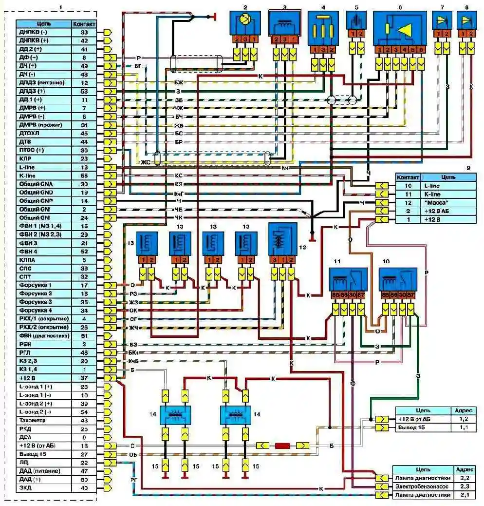
The electrical circuit of the engine control system is shown in the figure.
The ZMZ-402 and ZMZ-4021 engines are equipped with a non-contact ignition system, consisting of a transistor switch, ignition distributor type 19.3706, ignition coil type B116 or B116-01, candles and high-voltage and low-voltage wires.
The ignition distributor with a built-in Hall sensor produces voltage pulses, which the switch converts into current pulses in the primary winding of the ignition coil.
")

")
")
")
")
")
")
")