The microprocessor ignition system is designed to ignite the working mixture in the engine cylinders by setting the optimal ignition timing for a given engine operation mode
This system controls the PID Economizer Solenoid Valve.
With the help of a microprocessor ignition system, more economical engine operation is achieved; with an increase in its power indicators, the operation of the engine with detonation is excluded and the standards for exhaust toxicity are met.
This system is more durable and reliable than the classic ignition system.
There are no parts subject to wear (except spark plug electrodes).
On some cars, the MIKAS 7 control unit can be installed. 1.243.376-3-01.
- - generation of electric current pulses for the operation of the EPHX solenoid valve;
- - ensuring the operation of the entire system in a standby mode (in case of failure of individual elements of the system);
- - system troubleshooting.
The main element of the unit - the microprocessor - performs all calculations and generates all the necessary data to ensure the operation of the ignition system and EPHH. The unit works with the following sensors and assemblies:
- - crankshaft position and speed sensor (synchronization sensor);
- - absolute air pressure sensor in the engine intake pipe;
- - engine temperature sensor;
- - knock sensor;
- - ignition coils;
- - EPHX solenoid valve;
- - diagnostic control lamp.
The microprocessor ignition system and EPHH work as follows.
When the ignition is turned on, the warning light on the instrument panel lights up. At this time, the microprocessor operates in self-diagnosis mode.
After the end of this mode, the indicator lamp goes out if no malfunctions are detected, or lights up if a malfunction is detected.
If the signaling device goes out, the system is operational and ready for operation.
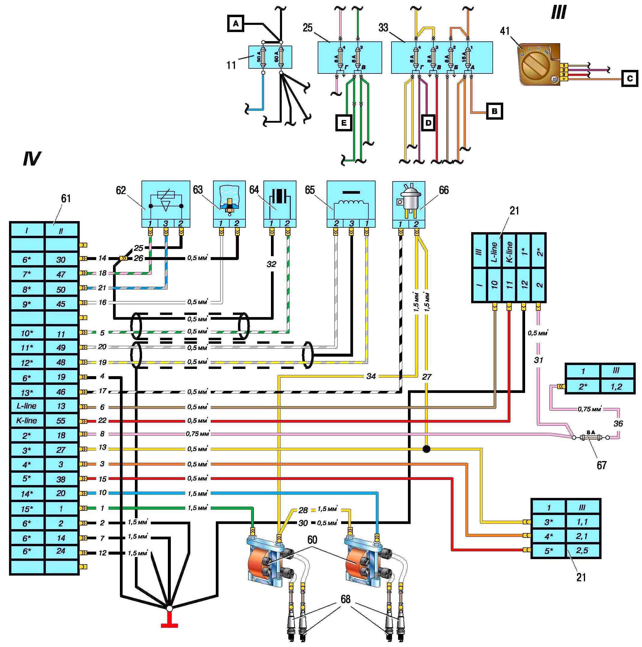
When the engine is cranked by the starter, based on signals from the crankshaft position sensor, the control unit delivers electrical current pulses to the ignition coils to ensure the operation of the spark plugs in accordance with the firing order of the engine cylinders 1-3-4-2.
High voltage from each ignition coil is simultaneously applied to two candles:
- - to the spark plug in the cylinder where the compression stroke of the working mixture occurs (for example, the 1st cylinder) and the electric discharge that ignites it;
- - at the same time, an electric discharge occurs in the second candle in the fourth cylinder, where the exhaust gas cycle occurs, this discharge does not affect the operation of the engine.
Faults in the ignition system and EPHH
The control unit has a self-diagnosis mode, with which you can determine the malfunctions in the system.
If the control unit in the self-diagnosis mode cannot determine the malfunction, then it is necessary to use a special device DST-2 with the appropriate cartridge (cassette with the program).
In this case, you must follow the instructions supplied with the device.
The control unit in the self-diagnosis mode issues light codes to the control lamp.
Each malfunction has its own digital code. The digital code is determined by the number of switching on of the control lamp.
First, the number of lamp turns on is counted to determine the first digit of the code (for example measures, number 1 - one short inclusion of 0.5 s, number 2 - two short inclusions, then there is a pause of 1.5 s.
After it, the number of inclusions is counted to determine the second digit of the code, then the third, after which there is a pause of 4 seconds, which determines the end of the code).
If the code is three-digit, the first digit is displayed for 1 second.
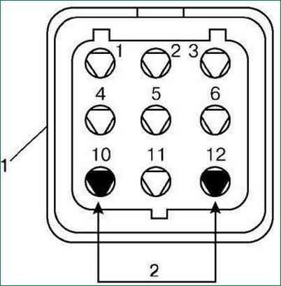
To put the control unit into self-diagnosis mode:
- - disconnect the battery for 10-15 seconds and reconnect it;
- - start the engine and let it idle for 30-60 seconds, - connect the terminals of the diagnostic socket with a separate wire according to the figure.
The socket is installed in the engine compartment on the bulkhead on the left side.
After the control unit is switched to the self-diagnosis mode, the control lamp should flash code 12 three times, which indicates the beginning of the self-diagnosis mode.
The following codes will display an existing fault or multiple faults. Each code is repeated three times.
After all codes of existing faults are displayed, code 12 is displayed three times and the indication of codes is repeated.
If the control unit cannot determine the malfunction or there are no malfunctions, code 12 is displayed. Diagnostic codes are shown in the table.
Code No. - Fault
- 12 - Self-test mode enabled
- 15 - Short circuit in the absolute air pressure sensor circuit
- 16 - Absolute air pressure sensor circuit open
- 21 - Short circuit in the engine temperature sensor circuit
- 22 - Open circuit in engine temperature sensor
- 25 - Low voltage in the vehicle's on-board network
- 51,52, 61-65 - Control unit failure
- 53 - Malfunction of the crankshaft position sensor or high level of interference in the vehicle's on-board network
- 181 - Short circuit in the diagnostic indicator lamp circuit (only detected by the DST-2)
- 182 - Open circuit of the diagnostic indicator lamp (detected by the DST-2)
- 197 - Short circuit in the EPHX valve circuit
- 198 - EPHX valve open circuit
Engine crankshaft position sensor (timing)
The inductive sensor determines the angular position of the engine crankshaft, the synchronization of the control unit with the engine's working process and its speed.
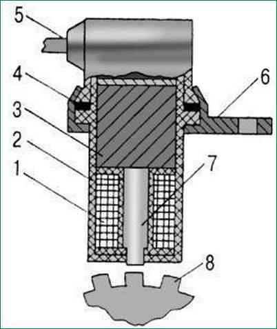
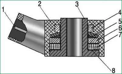
The knock sensor is installed on the right side of the cylinder block in the area of the fourth cylinder.
Operating the engine with knocking can lead to the destruction of engine parts (for example, piston, head gasket, etc.
The main elements of the sensor: quartz piezoelectric element 7 and inertial mass 6 (washer). When the engine is running, vibration of its parts occurs.
The inertial mass 6 of the sensor acts on the piezoelectric element 7; electrical signals of a certain size and shape arise in it.
The occurrence of detonation in the engine operation sharply increases the vibration, which increases the amplitude of the voltage of the electrical signals of the sensor.
Electrical signals from the sensor are transmitted to the control unit.
According to the knock sensor signals, the control unit corrects the ignition timing until detonation stops.
If the sensor or its electrical circuits fail, the control unit signals the driver by turning on the warning lamp.
The correctness of the sensor can only be checked when the engine is running using the DST-2 device.
Faulty sensor should be replaced
Temperature sensor

The coolant temperature sensor is a semiconductor element that changes its conductivity depending on the ambient temperature.
The sensor is installed in the thermostat nozzleata and is designed to determine the temperature of the engine coolant.
The sensor is included in the electronic circuit of the control unit, which, by the magnitude of the voltage drop in the sensor circuit (depending on temperature), corrects the ignition timing.
If a malfunction occurs in the sensor or in the sensor circuits, the control unit signals the driver by turning on the warning lamp.
The correctness of the sensor must be checked with the DST-2 device; in its absence, by the magnitude of the voltage drop in the sensor circuit at different temperatures.
checked by the DST-2 device as part of the vehicle.
Ignition coil
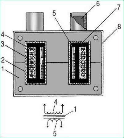
Ignition coils are designed to generate high voltage electric current to ignite the working mixture in the engine cylinders.
Ignition coils (2 pcs.) are mounted on top of the engine.
The ignition coil is a transformer. The primary winding 5 is wound on the magnetic circuit 1, and the secondary winding 3 is wound on top of it in sections.
The windings are enclosed in a plastic case 2.
The space between the windings is filled with compound 7.
There are low and high voltage terminals on the case 6.
Low voltage electrical pulses are supplied to the ignition coil from the control unit.
In the ignition coil, they are transformed into high voltage electrical impulses, which are transmitted through wires to the candles.
Electric discharge occurs simultaneously in two candles of the first and fourth cylinders or the second and third cylinders.
For example, one electrical discharge occurs in the candle of the first cylinder when the compression stroke ends there; the second discharge occurs in the candle of the fourth cylinder when the exhaust stroke occurs there.
Electrical discharge in the spark plug of the fourth cylinder during the exhaust stroke does not affect the operation of the engine.
With further rotation of the crankshaft, an electrical discharge will occur in the fourth candle, causing high voltage leakage and insulation breakdown.
If oil gets on the wires, they should be wiped with a rag soaked in gasoline.
If necessary, check the condition of the current-carrying core of the wire with an ohmmeter.
The resistance of the wires to the 1st and 2nd cylinders should be no more than 1000 Ohms, and the wires to the 3rd and 4th cylinders - no more than 900 Ohms.
Spark plug tips
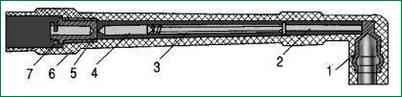
High voltage wires are connected to candles through special lugs
The device of the tip is shown in Figure 8
The resistance of a good tip should be no more than 8000 ohms.
")

")
")
")
")
")
")
")