The camshaft position sensor (0232103006 or 406.3847050-10) is installed in the end of the cylinder head on the left side of the flywheel
The sensor is a semiconductor device based on the Hall effect
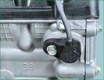
The sensor informs the control unit about the position of the TDC of the piston of the first cylinder during the compression stroke, which is necessary to comply with the fuel injection sequence according to the order of operation of the cylinders.
If the sensor or its circuits fail, the control unit turns on the KMSUd signaling lamp on the instrument panel, switches to standby mode with fuel supply to all cylinders simultaneously and stores a fault code in memory (see "diagnostics of the control system").
Turn off the ignition and disconnect the "negative" terminal of the battery.
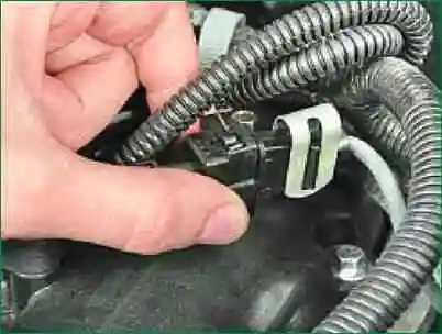
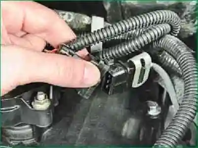
Squeezing the spring clip, disconnect the pads of the phase sensor harness
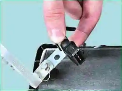
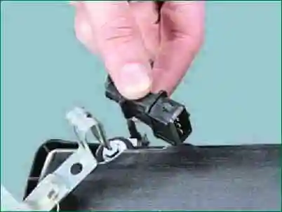
Unclench the spring holder of the sensor wiring harness block and remove the block from it
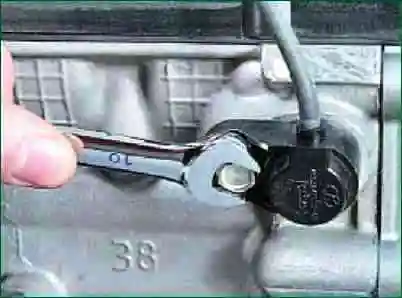
Using the “10” key, we unscrew the bolt securing the camshaft position sensor to the cylinder head.
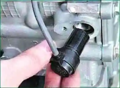
Remove the sensor.
The sensor is sealed with a rubber ring. A heavily compressed or deformed ring is replaced
Sensor test
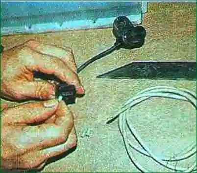
In order not to short-circuit the sensor contacts, we put short pieces of a PVC tube of small diameter on the pins of its connector,
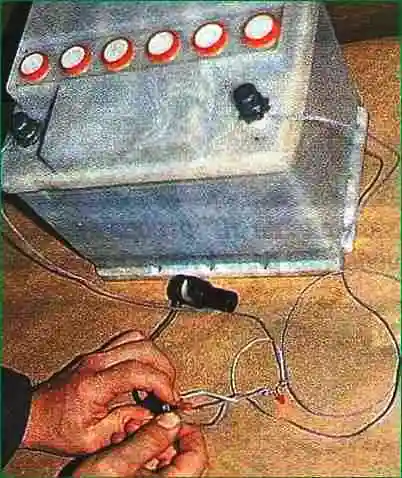
by inserting the bare ends of the wires into them, and the output of the resistor, we assemble the circuit
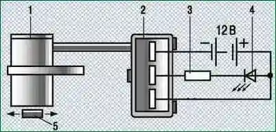
Camshaft position sensor test circuit
After making sure that the circuit is assembled correctly, we connect the wires to the battery terminals. In this case, the LED should light up and go out.
When moving a screwdriver blade near the end of the sensor, a working sensor should respond by briefly turning on the LED.
We replace the defective sensor.
Install the camshaft position sensor in reverse order.


