Motors are equipped with a friction fan drive designed to turn the fan on and off depending on operating conditions
The use of a friction drive allows you to:
Ensure optimal engine thermal conditions.
Reduce fuel consumption by reducing power losses for fan operation.
To increase the reliability of the gear drive of the engine by reducing the dynamic loads on the gears.
Ensure vehicle roaming without removing the fan.
Shorten engine warm-up time.
Improve comfort by maintaining the right climate in the cab and reducing noise.
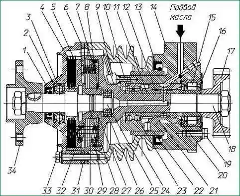
Fan drive: 1 - cuff; 2 - cover; 3 - bearing; 4 - driven disk; 5 - drive drive; 6 - gasket; 7 - squeezing spring; 8 - thrust ring; 9 - scoop tube; 10 - screw; 11 - spacer sleeve; 12 - sealing ring; 13 - cuff; 14 - body; 15 - bearing; 16 - thrust flange; 17 - gear; 18 - drive shaft; 19 - bolt; 20 - washer; 21 - bushing; 22 - spacer bushing; 23 - bearing; 24 - pulley; 25 - driven shaft; 26 - bearing; 27- push clip; 28 - sealing ring; 29 - sealing ring; 30 - piston; 31 - piston stop; 32 - pressure spring, 33 - bolt; 34 - fan hub.
Design and operation of the fan drive
Fan drive systems can be made with a mechanical switch (in spare parts for engines manufactured before 2003) or with electromagnetic control (engines manufactured since 2003) and therefore have a number of design differences.
Design and operation of a fan drive with a mechanical switch
The friction drive can operate in three modes: automatic, permanently on and permanently off.
The fan is controlled by a switch.
The fan is off when the engine is off.
After starting the engine, the fan impeller can rotate due to friction in the bearings and other mating parts of the disc clutch at a frequency of 200÷500 rpm.
When the temperature state of the engine is close to the highest optimum (+85˚-+93˚ С), the oil from the switch under pressure enters the fitting 13 (Fig. 1) of the housing 14.
Further through the hole in the housing, the radial holes in the bushings 10 and 22 enter the axial hole of the drive shaft 18, and from there to the piston 30.
The piston begins to move, transferring forces through springs 32 to the holder, which presses on disks 4 and 5, choosing the gaps between them.
After compression of the driving and driven disks, the driven shaft 25 with the impeller begins to rotate at the operating frequency.
After the temperature condition of the engine reaches a value close to the lowest optimum, the switch stops the oil supply.
The oil under the piston 30, under the action of centrifugal forces, as well as springs 7, 32, moves through the drainage holes through special channels into the internal cavity of the front cover 2 and pulley 24.
With the help of scoop tube 9 and further through the channels in the housing, oil enters the engine crankcase.
As the cavity under piston 30 is freed from oil, it moves under the action of springs 7 and 32.
The friction drive discs move apart and the fan turns off.
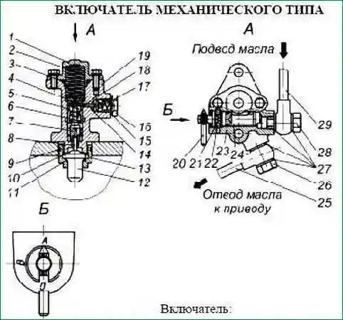
The mechanical type switch (Fig. 2) is combined with a temperature sensor and a manual mode switch and is installed on the engine water pipe.
The switch is used to control the friction drive clutch. Its mode of operation is set using the manual switch 20, which has three positions:
- - position "A" - automatic;
- - position "B" - always on;
- - position "O" - permanently off.
Oil from the central oil channel of the block through the inlet pipe 29 enters the switch.
When the lever is in the "B" position, the oil passes freely through the switch and enters the drive through the outlet tube 25, including oh it.
When the lever is in the ″O″ position, no oil enters the drive. Drive disabled.
When the lever position ″A″, the friction drive is switched on and off automatically depending on the temperature of the engine coolant.
When the coolant temperature is above +70ºС, the piston 8 of the sensor 12 is pushed out of the housing as a result of the volumetric expansion of the sensor filler.
Piston 8, resting against the pusher 7, raises it, simultaneously compressing the spring 6 of the spool 5.
The spool of circuit breaker 5 remains stationary, because held by the ball 18 of the latch 14.
When the coolant temperature is about +85ºС, pusher 7 touches spool 5, ball 18 leaves the fixing groove, spool 5 moves sharply in the direction of pusher 7.
The ball 18 enters another locking groove, the spool 5 stops and takes a position in which the cavity into which the oil is supplied is connected to the cavity that drains the oil.
Oil flows through the tube to the friction drive of the fan.
As the temperature of the coolant decreases, the piston of the sensor 8 begins to move into the sensor 12 under the action of the spring 6.
When the coolant temperature is +70ºС, the reverse movement of the spool 5 occurs, which closes the inlet and outlet cavities, stopping the oil from reaching the actuator. The drive is switched off.
Attention! When preparing to overcome the ford, it is necessary to set the fan drive switch to the “O” position (permanently off).
Design and operation of a fan drive with an electromagnetic switch
The device and principle of operation of the friction clutch of the fan drive are similar to the previous one, but the design of a number of parts has some peculiarities.
Electromagnetic switch
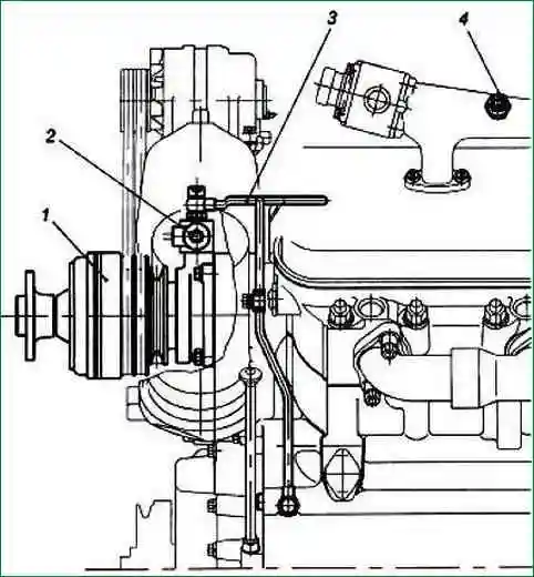
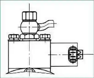
Features of the operation of the electromagnetic switch (Fig. 3-7) are that from the thermal relay installed on the right water manifold, an electrical signal is sent through the relay to the solenoid valve, which controls the flow of oil into the drive clutch.
The drive mode switch in this case is located in the cab and controls the operation of the solenoid valve also by an electrical signal.
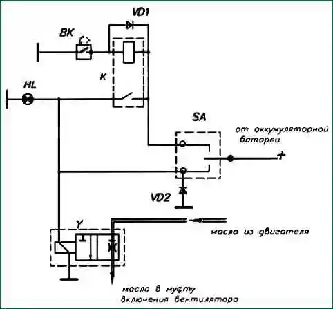
The circuit for switching on the fan clutch is electrical, in principle (Fig. 3) includes the following elements:
- - VK Thermal relay 661.3710-01;
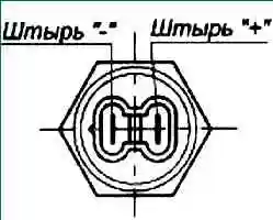
- - Y Solenoid valve KEM 32-20*;
- - HL Pilot lamp;
- - SA Switch 51.3709**;
- - VD1, VD2 Diode D247A**;
- - K Relay 11.3747**
* - The fan drive is equipped with a KEM 32-20 solenoid valve with an on-board network voltage of 24 V.
** - The electrical circuit diagram, therefore, it can be modified, including other components that are selected by enterprises-consumers of power units.
Functions of the elements of the electrical circuit diagram:
- 1. The SA switch is located in the cab.
- 2. The SA switch has three positions:
- "Disabled" - the fan is turned off regardless of the engine temperature.
- "Enabled" - the fan is on regardless of the engine temperature.
- "Automatic" - the fan is turned on by a thermal relay depending on the temperature of the engine.
- 3. HL - control lamp turns on when the fan is running.
Fan drive repair
Removing and disassembling the drive
- 1. Loosen the mounting bolts and remove the fan impeller.
- 2. Loosen the tensioners of the air compressor belt and the generator belt, remove the belts from the fan drive pulley.
- 3. Disconnect the voltage supply wires to the solenoid valve, dismantle the oil supply pipe by unscrewing its fastening bolt from the valve fitting, and, having unscrewed the fastening bolts, with Remove the valve together with the gasket from the fan drive.
- 4. Unscrew the fastening bolts and nuts, carefully, without damaging the gasket, remove the fan drive from the engine.
- 5. Unscrew the fastening bolts and remove the cover 2 from the drive (see Fig. 1) complete with the hub and the driven shaft 25, remove the package of driving and driven disks 4 and 5 from the drive shaft 18, as well as the piston 30 assembled with stop 31 and pressure clip 27.
- 6. Fix the drive gear 17 from rotation, unscrew the nut of its fastening.
Using any suitable puller, press the gear off the drive shaft.
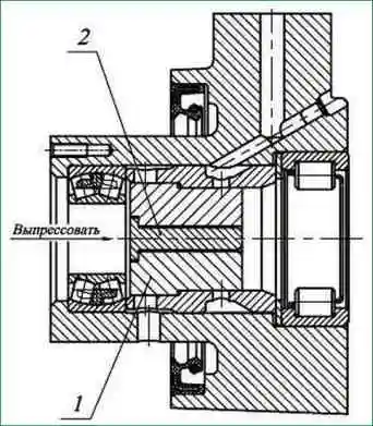
7. Press out the drive shaft. In this case, the pulley 24 must be fixed in the axial direction in order to avoid breakage of the scoop tube 9.
After that, remove the inner cage of the rear bearing 15 and the inner spacer sleeve 11 together with the sealing rings 12 from the drive housing 14.
8. Unscrew the fastening screws 10, remove the scoop tube and the compressor and generator drive pulley.
9. Loosen the mounting bolts 19 of the thrust flange 16, press out the outer spacer sleeve 21 and the outer race of the rear bearing.
In order to avoid transmission of axial force through the front bearing cage, pressing out must be carried out using a special tool, as shown in fig. 10 and 11.
After that, remove the front bearing from the housing.
Fan drive assembly
Assembly of the fan drive must be carried out in reverse order. In this case, the following requirements must be met:
- 1. Before assembly, all cuffs, rubber and metal sealing rings, as well as bearings must be lubricated with diesel oil.
- 2. Pressing the front spherical bearing into the housing must be done using a mandrel that does not allow the inner race to skew relative to the outer race, as well as the transfer of axial force through the cage.
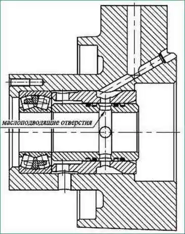
- 3. The spacer sleeves must be installed in the drive housing as shown in the figure to ensure that the oil holes are aligned.
- 4. When assembling a package of friction discs, the alternation of leading and driven discs should be as shown in fig. 1. In this case, the drive disks must be installed so that the direction of the squeezing whiskers is counterclockwise, if you look at the drive from the side of the fan hub.
- 5. When assembling the fan drive, the following screw connections must be tightened to a controlled torque:
- - thrust flange bolts 1.8-2.0 Nm (18-20 kgf m);
- - scoop tube screws 0.5-0.8 Nm (4.9-7.8 kgf m);
- - drive cover bolts 2.0-2.5 Nm (19.61-24.51 kgf m);
- - gear nuts and hub 16-20 Nm (156.9-196.1 kgf m).
When assembling the fan drive, sealant UG-9 TU 2257-407-00208947-2004 or UG-10 TU 2257-408-00208947-2004 must be applied to the gear nut thread entry.
Rust, oil and other contaminants in the threaded connection are not allowed.
For the assembled fan drive, the rotation of the pulley relative to the housing must be free, without jamming.
The rotation of the fan hub relative to the fixed housing and the pulley must also be free, without jamming.