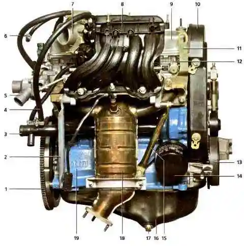
Engine - gasoline, four-stroke four-cylinder in-line with an overhead camshaft and liquid cooling
Eight-valve engines with a working volume of 1.6 liters are based on the VAZ-2111 engine.
They have a cylinder block increased in height by 2.3 mm and an original crankshaft.
The cylinder diameter remains the same - 82 mm, the piston stroke is increased to 75.6 mm, in contrast to 71 mm for the base engine.
Oil jets are installed in the main bearings.
The cylinder head has one camshaft, eight valves and eight valve lifters with shims.
The camshaft bearings are made in the head.
Two camshaft bearing housings are bolted to the upper plane of the head.
The gas distribution mechanism is closed from above by a cap with an oil filler neck.
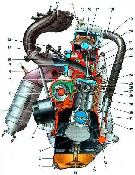
The camshaft and coolant pump are driven by a toothed belt from a toothed pulley mounted on the engine crankshaft.
The tension of the belt and the direction of its movement along the pulleys is carried out by the tension roller.
The cylinder block is cast iron, with cylinders machined in it.
The internal cavities of the block for the coolant are formed during its casting, and the oil supply channels are made by drilling.
Five crankshaft main bearings are located at the bottom of the cylinder block.
Main bearing caps are not interchangeable and are marked with the bearing serial number starting from the crankshaft pulley.
In the cover of the second main bearing, there are two threaded holes for the oil intake mounting bolts.
Steel-aluminum main bearing shells are installed in the supports and covers.
On both sides of the third main bearing support, sockets are made for installing thrust half rings that prevent axial movement of the crankshaft.
The front half-ring is steel-aluminum, the rear half-ring is cermet, yellow on both sides.
Pistons cast from aluminum alloy. Each piston has two compression rings and one oil scraper ring.
Lower scraper-type compression ring with a groove and a sharp edge on the lower plane.
A spring expander is installed inside the oil scraper ring.
Pins - floating type (fixed in the pistons with two spring retaining rings) or fixed Shrink fit into the top end of the connecting rod.
A steel-bronze bushing is pressed into the upper head of the connecting rod.
The connecting rod caps are not interchangeable and only fit in one position on the connecting rod.
The oil pan is attached to the cylinder block from below.
Engine lubrication system combined - under pressure and spray.
The oil pump is an internal gear type driven by the front end of the crankshaft.
Through the oil intake, the pump takes oil from the oil pan and pressurizes it into the channels of the engine lubrication system.
To control the amount of oil in the sump, a measuring probe is installed - a level indicator.
Oil filter - full-flow, with a paper filter element and a check valve that prevents oil from flowing out of the lubrication system channels into the oil pan after the engine has stopped.
Oil jets are installed in the main bearings.
Oil from the nozzles is supplied to the internal surfaces of the pistons to cool them.
Part of the oil falls on the upper heads of the connecting rods and flows through the conical holes made in them onto the piston pins, lubricating them.
Channels are drilled in the body of the crankshaft. Oil flows through them to the connecting rod journals, lubricating them.
Oil enters the crankshaft channels from the cylinder block through holes in the main bearing shells and main journals.
Technological openings of the channels are closed with stamped steel plugs.
On the left side of the block there is a cavity for installing a coolant pump and a tide for installing an oil filter.
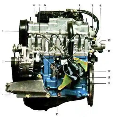
The generator is driven by a V-ribbed belt from the engine crankshaft pulley.
The intake manifold reservoir is made of plastic.
The exhaust manifold is steel, combined with a catalytic converter, Its connection to the head is sealed with a two-layer metal gasket.