Drain the oil from the crankcase.
Remove the oil pan.
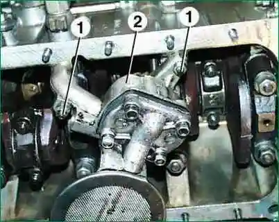
On the engine mod. 402 unscrew the two nuts 1 and remove the pump 2 with the receiver as an assembly.
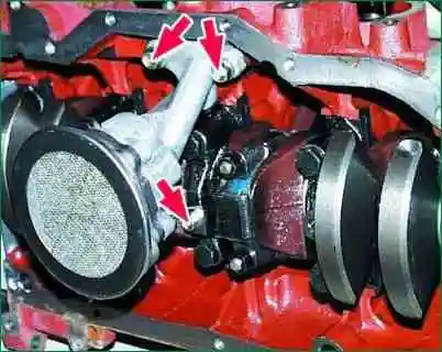
On the engine mod. 406 unscrew the three bolts and remove the pump with the receiver assembly.
Disassembly
Oil pumps for engines mod. 402 and 406 are similar in design.
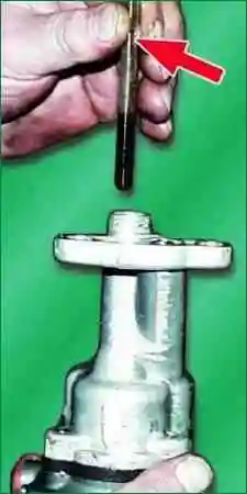
Remove the hexagonal shaft of the oil pump drive.
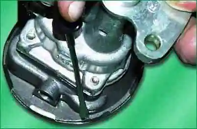
Remove the mesh from the receiver by folding the edges of the mesh.
Remove four bolts 3 and remove receiver 2 and baffle 1
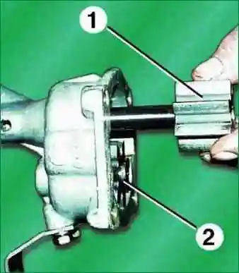
Remove the drive gear 1 with the roller and the driven gear 2. If you need to remove the drive gear from the roller, knock out the pin.
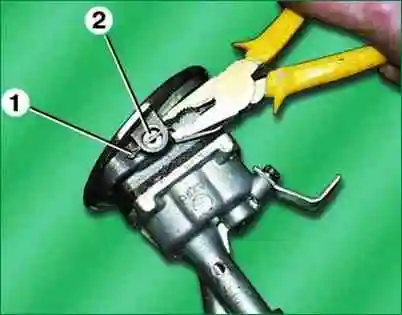
Remove cotter pin 1, washer 2, pressure reducing valve spring and plunger installed under washer 2.
Wash the pump parts with gasoline and blow with compressed air.
More details:
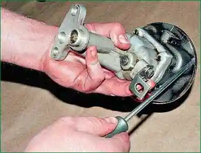
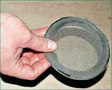
Use a screwdriver to bend the antennae of the mesh frame and remove the mesh.
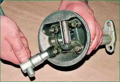
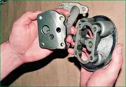
With a “12” head, unscrew the four bolts and remove the pump inlet pipe.
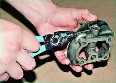
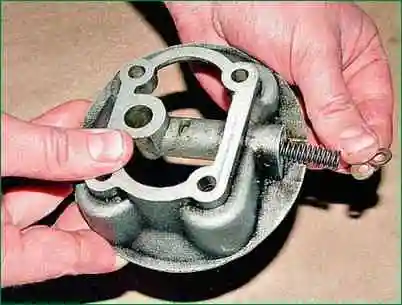
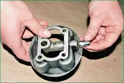
Remove the cotter pin from the hole and remove the shims and spring from the channel, as well as the pressure reducing valve plunger.
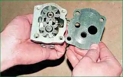
Remove the partition from the pump.
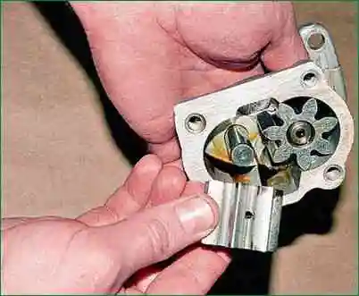
We take out the driven and driving gears.
Inspection and repair
If there is wear on the partition (cover for mod. 402), it must be sanded so that no traces of wear remain.
Inspect the hull. If it is badly worn, you need to replace the pump.
The gears in the pump housing must turn completely freely.
The pressure relief valve plunger must move completely freely in the body.
Inspect the relief valve spring. If cracks are visible on it or the coils are broken, replace the spring.
The length and stiffness of the spring are selected at the factory in such a way that the operation of the pressure reducing valve is optimal, therefore, the length and stiffness of the spring must not be changed in any way.
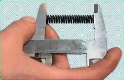
The length of the spring in the free state should be 50 mm, the force to compress the spring by 10 mm should be 46 N (4.6 kgf) for engine mod. 406.
For engine mod. 402, in order to compress the spring to a length of 40 mm, it is necessary to apply a force of 43.5–48.5 N (4.35–4.85 kgf).
If the spring does not meet at least one of these requirements, it must be replaced.
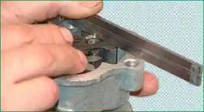
Measure the gap between the ends of the gears and the plane of the pump housing with a flat feeler gauge, applying a ruler or caliper to the plane of the housing.
The gap should be 0.040-0.140 mm
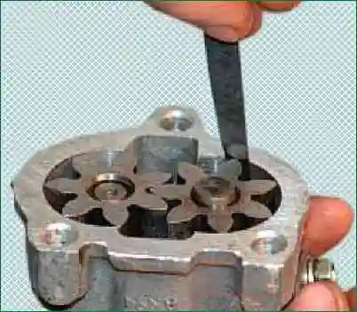
Measure the gap between the outer diameters of the gears and the housing with a flat feeler gauge, it should be 0.120-0.215 mm.
If the end and radial clearances exceed the specified values, replace the housing.
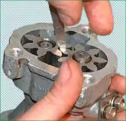
Measure the gap between the gear teeth with a flat feeler gauge, it should be 0.15 mm.
If the gap is greater than the specified value, replace the gears.
Replace worn or damaged parts.
With maximum cleanliness during assembly, assemble the pump in the reverse order of disassembly.
Install the pump in the reverse order of removal. Don't forget to add oil to the engine.
Assembly
The pump is assembled in the reverse order.
When assembling the motor pump mod. 402 under the pump cover, you need to put a cardboard gasket 0.3 mm thick.
It is forbidden to install a gasket of a different thickness or use sealant, paint, etc. when installing the gasket, as this will reduce the performance of the pump.
Install the pump in the reverse order of removal.


