The crankshaft is made of high-quality steel and has five main and four connecting rod journals, connected by cheeks and mated with transition fillets
For uniform alternation of working strokes, the crankpins of the crankshaft are located at an angle of 90°.
Two connecting rods are attached to each crankpin (Figure 2):
- one for the right and one for the left rows of cylinders.
The crankshaft is hardened by nitriding to a depth of 0.5-0.7 mm, the hardness of the hardened layer is at least 600 HV.
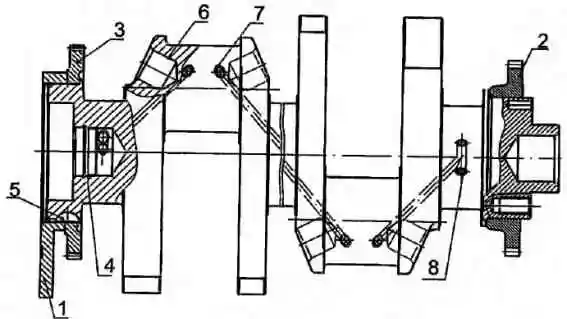
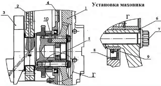
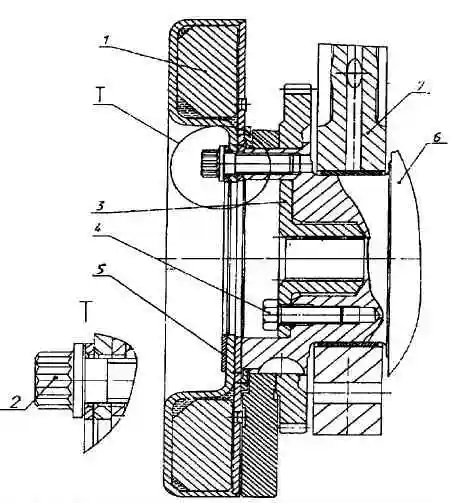
Oil is supplied to the connecting rod journals through holes in the main journals 8 and holes 7 (Figure 1), which do not intersect with the lightening holes 6 in the connecting rod journals.
To balance inertial forces and reduce vibrations, the crankshaft has six counterweights, stamped integrally with the crankshaft cheeks.
In addition to the main counterweights, there is an additional removable counterweight 1, pressed onto the shaft; its angular location relative to the crankshaft is determined by key 5.
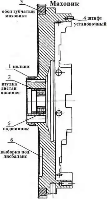
To ensure the required imbalance, sample 6 is performed on the flywheel (Figure 3)
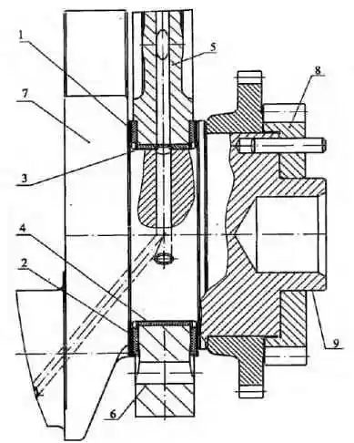
On the crankshaft shank there is a journal 9 (Figure 4), along which the crankshaft gear 8 and flywheel 1 are centered (Figure 5).
At the rear end of the crankshaft there are ten threaded holes M16x1.5-6N for fastening the crankshaft gear and flywheel, at the front end there are eight threaded holes M 12x1.25-6N for fastening the torsional vibration damper.
A plug 4 is installed in the cavity of the crankshaft nose (Figure 1), through the calibrated hole of which the spline shaft of the front power take-off drive is lubricated.
The crankshaft is secured against axial movements by two half-rings 1 and two half-rings 2 (Figure 4), installed in the grooves of the rear main support of the cylinder block, so that the side with the grooves is adjacent to the thrust ends of the shaft.
On the toe and shank of the crankshaft (Figure 1) gears are installed to drive oil pumps 3, 2 and drive the gas distribution mechanism 8 (Figure 4).
The crankshaft is sealed by a rubber cuff 8 (Figure 5), with an additional sealing element - boot 9.
The cuff is located in the flywheel housing 4.
The cuff is made of fluorine rubber using the technology of molding the working sealing edge directly in the mold.
Nominal diameters of crankshaft journals:
- - radical 95 -0.015 mm,
- - connecting rod 80-0.013 mm.
Eight repair sizes of liners are provided for engine restoration.
On designation crankshaft bearings, the diameter of the crankshaft main journal, and the diameter of the hole in the cylinder block for these bearings are indicated in Table 1

The designation of the bearings for the lower head of the connecting rod, the diameter of the crankpin journal of the crankshaft, the diameter of the hole in the crank head of the connecting rod for these bearings are indicated in Table 2

Inserts 7405.1005170 P0, 7405.1005171 P0, 7405.1005058 P0 are used when restoring an engine without grinding the crankshaft. If necessary, polish the crankshaft journals.
When grinding the crankshaft along the main journals of 94 mm or less or along the connecting rod journals of 79 mm or less, the crankshaft must be re-nitrided.
The tolerance limits for the diameter of the crankshaft journal, the diameter of the hole in the cylinder block and the diameter of the hole in the crank head of the connecting rod when rebuilding the engine must be the same as for the nominal dimensions.
Engine crankshaft mod. 740.30-260 has the following main differences from crankshafts of engines mod. 740.10 and 7403.10:
- - hardening is carried out by nitriding instead of hardening with high frequency current;
- - dirt-catching cavities in the connecting rod journals are excluded, oil is supplied to the connecting rod journals from the holes in the main journals with straight holes that do not intersect with the lightening holes in the connecting rod journals;
- - there is a neck on the shank, along which the crankshaft gear and flywheel are centered.
These differences make it impossible to use crankshafts from mod. 740.10 and 7403.10 for engines mod. 740.30-260.
Main and connecting rod bearings (Figures 2 and 4) are made of steel strip coated with a layer of lead bronze 0.3 mm thick and a layer of lead-tin alloy 0.022 mm thick. and a layer of tin 0.003 mm thick.
The upper 3 and lower 4 main bearing shells are not interchangeable.
The upper liner has a hole for oil supply and a groove for its distribution.
Both shells 4 of the lower connecting rod head are interchangeable.
The liners are secured against rotation and lateral displacement by protrusions (whiskers) that fit into the grooves provided in the block and connecting rod beds, as well as the bearing caps.
The liners have design differences aimed at increasing their performance when the engine is boosted by turbocharging, while the marking of the liners has been changed to 7405.1004058 (connecting rod), 7405.1005170 and 7405.1005171 (main).
It is not recommended to replace liners during repairs with serial ones marked 740, as this will significantly reduce engine life.
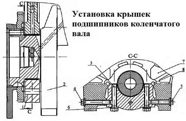
The main bearing caps (Figure 8) are made of high-strength cast iron.
The covers are secured using vertical and horizontal coupling bolts 3, 4, 5, which are tightened according to a specific pattern with a regulated torque (article - Tightening torques for KAMAZ diesel connections).
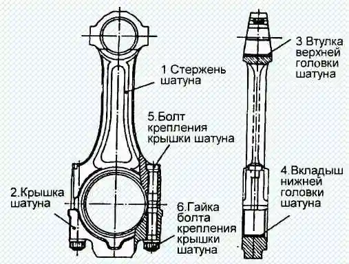
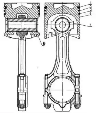
Connecting rod (Figure 2) is forged steel, rod 1 has an I-section.
The upper head of the connecting rod is one-piece, the lower one is made with a straight and flat connector. The connecting rod is finally processed as an assembly with a cover 2, so the connecting rod caps are not interchangeable.
A steel-bronze bushing 3 is pressed into the upper head of the connecting rod, and replaceable liners 4 are installed into the lower head.
The cover of the lower head of the connecting rod is secured using nuts 6 screwed onto bolts 5, previously pressed into the connecting rod rod.
The connecting rod bolts are tightened according to the scheme defined in the article Tightening torques for KAMAZ diesel connections.
On the cover and rod of the connecting rod there are pairing marks - three-digit serial numbers. In addition, the cylinder serial number is stamped on the connecting rod cover.
The
Flywheel (Figure 3) is secured with ten bolts 7 (Figure 5), made of alloy steel, at the rear end of the crankshaft and secured with a pin 10 (Figure 5) on the centering journal of the crankshaft 9 (Figure 4).
In order to avoid damage to the flywheel surface, washer 6 is installed under the bolt heads (Figure 5).
Tightening torque of the bolts The flywheel alignment is indicated in the article - Tightening torques for KAMAZ diesel connections.
A toothed rim 3 is pressed onto the machined cylindrical surface of the flywheel (Figure 3), with which the starter gear meshes when starting the engine.
Ring 1 with an outer chrome-plated surface is installed under the crankshaft seal collar.
The flywheel is made for one or two disc diaphragm clutches. Bearing 5 of the gearbox input shaft is installed in the internal bore of the flywheel.
When adjusting the fuel injection advance angle and thermal clearances in the valves, the flywheel is fixed with a clamp (Figure 9).
The flywheel design has the following main differences from the flywheels of engines 740.10 and 7403.10:
- - the angle of the groove for the retainer on the outer surface of the flywheel has been changed;
- - the diameter of the bore has been increased to accommodate the washer under the flywheel mounting bolts;
- - crescent sampling has been introduced to ensure the required imbalance;
- - the flywheel is attached to the end of the crankshaft using ten M16x1.5 bolts;
The listed changes make it impossible to install flywheels on engines 740.10 and 7403.10 during repair work.
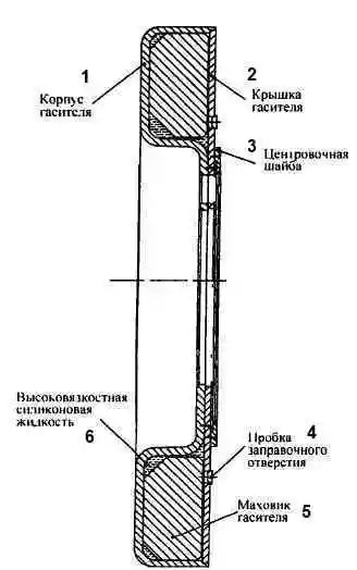
The torsional vibration damper (Figure 10) is secured with eight bolts 2 (Figure 11) on the front toe of the crankshaft.
The damper consists of a housing 1 (Figure 10) into which the damper flywheel 2 is installed with a gap.
The damper body is closed from the outside with lid 3.
Tightness is ensured by welding at the junction of the damper body and the cover.
Between the damper body and the damper flywheel there is a highly viscous silicone liquid, dosed before welding the cap.
The damper is centered using washer 6 welded to the body.
The damping of torsional vibrations of the crankshaft occurs by braking the damper body, mounted on the toe of the crankshaft, relative to the flywheel in a silicone liquid environment.
In this case, braking energy is released in the form of heat.
It is strictly forbidden to deform the body and cover of the damper during repair work.
An absorber with a deformed body or cover is not suitable for further use.
After installing the damper, check for clearance between the damper and the counterweight.
Piston 1 (Figure 12) is cast from aluminum alloy with a wear-resistant cast iron insert under the upper compression ring.
The piston head has a toroidal combustion chamber with a displacer in the central part, which is shifted relative to the piston axis away from the recesses for the valves by 5 mm.
The side surface is a complex oval-barrel shape with a reduction in the area of the holes for the piston pin. The skirt has a graphite coating.
There is a groove in its lower part that, if assembled correctly, prevents contact of the piston with the cooling nozzle when at bottom dead center.
The piston is equipped with two compression rings and one oil scraper ring.
Its distinctive feature is the reduced distance from the bottom to the lower end of the upper groove, which is 17 mm.
On the 740.30-260 engine, similar to other KAMAZ engine models, in order to ensure fuel efficiency and environmental performance, selective selection of pistons for each cylinder is used according to the distance from the axle and the piston pin to the bottom.
According to the specified parameter, the pistons are divided into four groups 10, 20, 30 and 40. Each subsequent group differs from the previous one by 0.11 mm.
Spare parts are supplied with pistons of the highest height, therefore, in order to avoid possible contact between them and the cylinder heads, in case of replacement it is necessary to control the clearance above the piston.
If the gap between the piston and the cylinder head after tightening its mounting bolts is less than 0.87 mm, it is necessary to trim the piston bottom by the amount missing to this value.
Installation of pistons from KAMAZ engines of other models is unacceptable
Compression rings (Figure 12) are made of high-strength cast iron, and the oil scraper ring is made of gray cast iron.
The upper compression ring has the shape of a double-sided trapezoid, with an internal recess at the upper end, and the second has the shape of a one-sided trapezoid.
During installation, the end with the “top” mark should be located on the side of the piston bottom.
The working surface of the upper compression ring 4 is covered with molybdenum and has a barrel shape.
Chrome is applied to the working surface of the second compression ring 5 and oil scraper ring 2.
Its shape on the second ring is a cone with a slope towards the lower end; for this characteristic feature the ring is called “minute”.
Minute rings are used to reduce oil consumption due to waste; their installation in the upper groove is unacceptable.
Oil scraper ring is box-type, 4 mm high, with a spring expander having a variable pitch of turns and a ground outer surface.
The middle part of the expander with a smaller pitch of turns when installed on the piston should be located in the ring lock.
Installing piston rings from other KAMAZ engine models may lead to increased oil consumption due to waste.
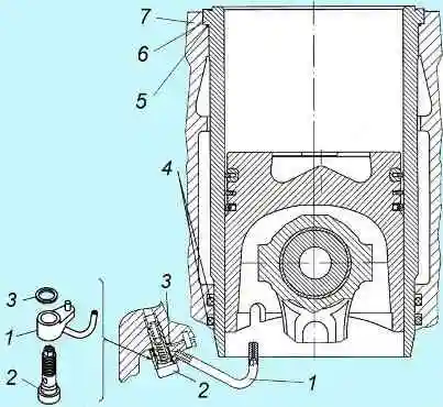
Cooling nozzles (Figure 13) are installed in the crankcase of the cylinder block and provide oil supply from the main oil line when it reaches a pressure of 80-120 kPa (0.8-1.2 kg/ cm 2), to the internal cavity of the pistons.
The valve located in each of the nozzles is adjusted to this pressure.
When assembling the engine, it is necessary to check the correct position of the injector tube relative to the cylinder liner and piston. Contact with the piston is not permitted.
The piston and connecting rod (Figure 12) are connected by a floating pin 3, its axial movement is limited by retaining rings 6.
The pin is made of chromium-nickel steel, the hole diameter is 22 mm. The use of pins with a 25 mm hole is unacceptable, as this disrupts the engine balance.
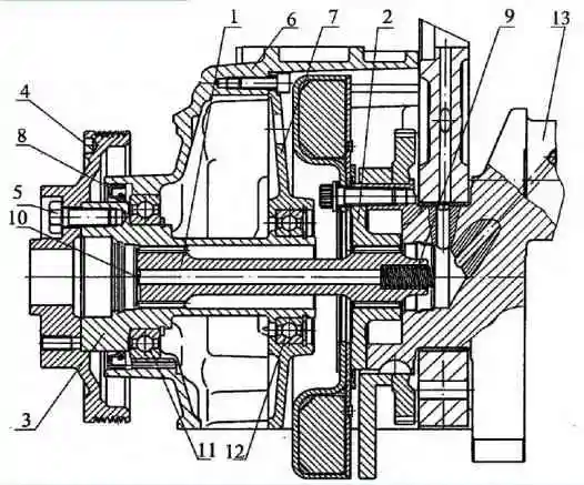
The front power take-off drive (Figure 14) is carried out from the toe of the crankshaft through the power take-off half-coupling 2, attached to the toe of the crankshaft 13 with eight special bolts M12x1.25.
The coupling half is centered relative to the crankshaft using the internal bore of the remote counterweight.
The torque from the coupling half is transmitted through the drive shaft of the units 1 and the power take-off shaft 3 to the pulley 4.
The power take-off shaft 3 is mounted on two ball bearings 11 and 12. The cavity is sealed with a cuff 8.
To reduce wear of spline joints, the drive shaft of the units is kept from axial movements by spring 9.