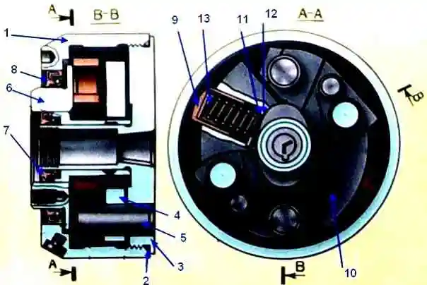
The fuel pump assembly is shown in fig. 1.
With a high-pressure fuel pump, the speed controller 5, the fuel priming pump 9 and the fuel injection advance clutch 4 are combined in one unit
Design and operation of the high pressure fuel pump
The high-pressure fuel pump consists of sections, separate pumping elements located in a common housing.
The number of sections is equal to the number of engine cylinders.
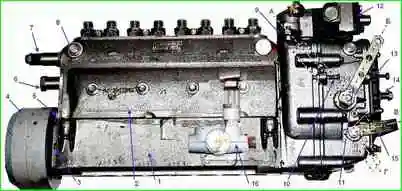
High pressure fuel pump models 806 and 807: 1 - high pressure fuel pump; 2 - side cover; 3 - shims; 4 - fuel injection advance clutch; 5 - pointer; 6 - cap of the rail of the fuel pump; 7 - bypass valve; 8 - plugs for air release; 9 - speed controller; 10 - bolt limiting the maximum speed; 11 - regulator control lever; 12 - boost fuel supply corrector; 13 - bolt limiting the minimum speed; 14 - buffer spring housing; 15 - stop bracket; 16 - fuel priming pump; A - lever position at maximum idle speed; B - position of the lever at the minimum idle speed; B - the position of the bracket during operation; G- position of the bracket when the feed is off
The arrangement of the fuel pump section is shown in fig. 2.
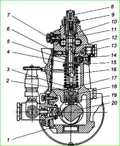
High pressure fuel pump section: 1 - pump housing; 2 - locknut; 3 - adjusting bolt; 4 - rotary sleeve; 5 - ring gear; 6 - set screw; 7 - plug for air release; 8 - fitting; 9 - pressure valve spring; 10 - discharge valve; 11 - pressure valve housing; 12 - plunger bushing; 13 - plunger; 14 - rail; 15 - upper spring plate; 16 - pusher spring; 17- lower spring plate; 18 - pusher; 19 - pusher roller; 20 - camshaft
Plunger pairs, discharge valves 10 and fittings 8 are installed in the pump housing 1, to which high-pressure pipelines are connected.
The discharge valve 10 and the valve body 11, as well as the plunger 13 with the sleeve 12 are precision pairs that can only be replaced as a set.
The plunger bushing is fixed from turning with screw 6.
Plunger 13 is driven by camshaft 20 via roller follower 18.
Spring 16 constantly presses the pusher against the cam through the lower plate 17.
The pusher is fixed from rotation by the pusher cracker, which enters the groove on the bore of the pump housing.
Adjusting bolt 3 is screwed into the pusher, which is locked with locknut 2 and serves to adjust the start of fuel supply.
The design of the plunger pair allows you to dose the fuel by changing the moment of supply at a constant start.
To change the amount of fuel supplied, the plunger in the sleeve 12 is rotated by the rotary sleeve 4 with the ring gear 5 engaged with the rack 14.
The angular displacement of the rotary sleeve relative to the ring gear with the screw loosened regulates the fuel supply by each section of the pump.
In the upper part of the pump housing there are inlet and outlet channels through which fuel enters the plunger pairs.
On the regulator side, the channels are plugged with plugs with sealing rubber rings, on the drive side they are interconnected by a transverse channel.
The fuel inlet and outlet lines are connected to the high pressure pump on the drive side. The air outlet is closed with plug 7 (Fig. 2).
The section works as follows
When the plunger 13 moves down under the action of the spring 16, fuel under slight pressure created by the fuel priming pump in the fuel supply channel of the pump housing enters the space above the plunger.
When the plunger moves up, the fuel is bypassed back into the fuel channel until the end edge of the plunger closes the bushing inlet.
With further upward movement of the plunger, the pressure in the space above the plunger increases.
When the pressure reaches a value greater than the force generated by the injector spring, the injector needle will rise and the process of injecting fuel into the combustion chamber of the engine cylinder will begin.
As the plunger moves further upwards, the spiral cut-off edge of the plunger opens a cut-off hole in the sleeve, which causes a sharp drop in fuel pressure in the injection line.
At this heat push valve 10 with an unloading belt after landing on the closing cone of the valve body 11 under the action of the spring 9 increases the volume in the fuel line between the nozzle and the valve.
This achieves a clear cut-off of the fuel supply.
The amount of fuel supplied is dosed by changing the moment of the end of the supply with its constant beginning.
When the rack is moved, the plunger rotates and the cut-off edge opens the bushing hole sooner or later, as a result of which the duration of the supply changes, and, consequently, the amount of fuel supplied.
There is an annular groove on the surface of the plunger, and a radial hole in the wall of the plunger sleeve to drain fuel that has leaked through the gap in the plunger pair.
The seal between the plunger sleeve and the pump housing is carried out by a rubber ring.
From the cavity around the plunger sleeve, the leaked fuel is discharged into the drainage channel passing along the pump housing, and then through the drainage pipeline into the fuel tank.
The camshaft is located at the bottom of the pump housing.
The camshaft rotates in tapered roller bearings and has an intermediate support.
Axial play of the camshaft in the range of 0.01-0.07 mm is provided by shims installed between the bearing cover and the pump housing.
The sections are connected to the pump speed controller via a rail.
The fuel pump rail moves in guide bushings pressed into the pump housing.
The end of the rail protruding from the pump is closed with a cap 6 of the fuel pump rail (Fig. 1).
The lubrication of the fuel pump is centralized, from the engine oil system.
Oil is supplied to the boost corrector, from where, merging into the cavity of the regulator, it enters the cavity of the pump camshaft
Speed controller
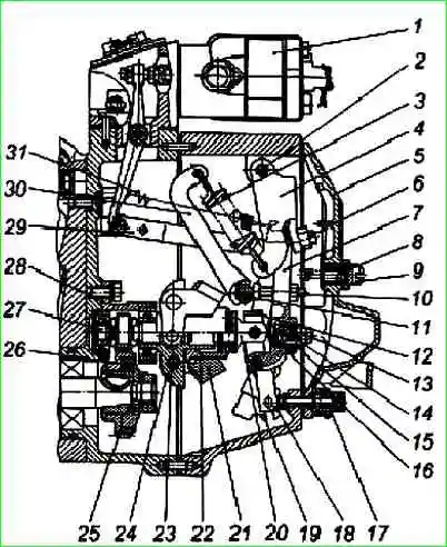
Rotational speed regulator: 1 - boost fuel supply corrector; 2 - axis of the two-arm lever; 3 - regulator spring; 4 - two-arm lever; 5 - cover of the inspection hatch; 6 - adjusting screw; 7- regulator lever; 8 - buffer spring; 9 - buffer spring housing; 10 - adjusting bolt; 11 - spring lever shaft; 12 - regulator earring; 13 - corrector; 14 - corrector spring; 15 - corrector spring housing; 16 - set of washers; 17- power adjustment screw; 18 - rail lever; 19 - wings; 20 - heel; 21 - regulator weights; 22 - cargo clutch; 23 - cargo axis; 24 - holder of goods; 25 - drive gear; 26 - crackers; 27 - roller holder loads; 28 - glass; 29 - rack rod; 30 - spring lever; 31 - rack lever spring
The speed controller 9 (Fig. 3) is a mechanical all-mode direct action with an overdrive gear for the load drive, with devices for adjusting the fuel supply and is designed to maintain the engine speed set by the driver by automatically changing the amount of fuel supplied depending on the change engine load.
In addition, the regulator limits the maximum engine speed and ensures that the engine operates in the required mode.
The regulator has a device to turn off the fuel supply at any time, regardless of the engine operating mode.
By automatically maintaining the speed mode under changing loads, the governor ensures economical operation of the engine.
The regulator is mounted on the rear end of the high pressure fuel pump.
The device of the speed controller is shown in fig. 3.
A drive gear 25 is mounted on the cone of the camshaft.
The rotation from the pump shaft to the drive gear is transmitted through rubber crackers 26, which smooth out the uneven rotation of the pump shaft.
The driven gear is made as one piece with the roller 27 of the load holder and is mounted on two ball bearings in the cup 28.
A weight holder 24 is pressed onto the roller, on the axes 23 of which weights 21 swing.
The weights with their rollers rest against the end of the clutch 22, which, through the thrust bearing and the heel 20, transmits the force to the regulator lever 7, suspended together with the two-arm lever 4 on the common axis 2.
The clutch with the thrust heel assembly rests at one end on the guide surface of the holder, and at the other end is hung on the earring 12, fixed on the regulator lever.
The heel of the regulator is connected by a common axis with the lever 18 of the rail and through the rod 29 - with the rail of the fuel pump.
A spring 31 of the rack lever is attached to the upper part of the rack lever, and a pin is pressed into the lower part, which enters the groove of the backstage 19.
Shaft 11 is rigidly connected to control lever 11 (see Fig. 1) and spring lever 30.
The regulator spring 3 is hooked to the lever, the force of which is transmitted from the two-arm lever to the regulator lever through the adjusting screw 6.
The regulator lever has an adjusting bolt 10, which rests against the shaft of the spring lever.
At the bottom of the regulator lever there is a positive corrector (pos. 13-16), designed to improve engine traction and reduce exhaust smoke.
The positive corrector consists of corrector 13, spring 14, corrector spring housing 15 and a set of washers 16.
The fuel supply is completely turned off by the stop mechanism, which consists of a backstage 19, a stop bracket 15 (Fig. 1) and a return spring located behind the stop bracket under the cover.
The link with the stop bracket is connected by a spring located inside the link and protecting the regulator mechanism from excessive force when the fuel supply is turned off.
During the operation of the engine, the rocker is pressed against the adjusting screw 17 by the force of the return spring (Fig. 3).
At the back, the speed controller is closed by a cover 5 of an inspection hatch with a buffer device, which ensures stable operation of the engine at minimum idle.
The buffer device consists of a spring 8, a housing 9 and a lock nut.
The speed controller is equipped with a fuel boost corrector to reduce the heat density and smoke in diesel exhaust gases at low speeds and transient conditions.
The turbo boost corrector provides the optimal amount of fuel supply depending on the air pressure supplied by the turbocharger to the engine cylinders.
In addition, the corrector protects the engine in emergency situations that occur when the turbocharging system fails.
The principle of operation of the boost corrector is that when the boost air pressure decreases, it acts on the fuel pump rail, changing the fuel supply.
The fuel boost corrector 12 (Fig. 1) is fixed on top of the fuel pump regulator housing.
The principle of operation and operation of the boost corrector are similar to those on the model 173 high-pressure fuel pump, see the article - "TNVD - 173".
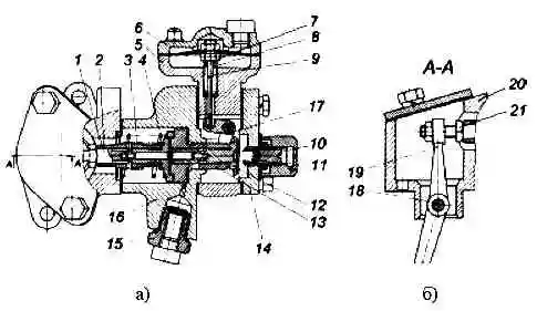
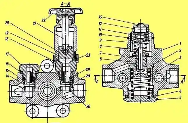
Fuel boost corrector: a) horizontal section: b) vertical section 1 - stop sleeve: 2 - stop; 3 - sleeve spring; 4 - piston spring; 5 - membrane housing; 6 - membrane cover; 7 - locknut of the membrane rod; 8 - spring; 9 - rod with a membrane; 10 - corrector spring housing; 11 - corrector spring; 12 - spool; 13 - piston; 14 - corrector cover; 15 - oil supply fitting; 16 - corrector housing; 17 - lever; 19 - lever axis; 19 - lever; 20 - spacer; 21 - lever adjusting bolt
The boost corrector device is shown in fig. 4
Basic adjustments provided by the design of the speed controller
- The minimum idle speed is regulated by the minimum speed limiting bolt 13 (Fig. 1) and the buffer spring housing 9 (Fig. 3).
- The maximum idle speed (the beginning of the rack ejection) is regulated by the maximum speed limiter bolt 10 (Fig. 1).
- The rated power (feed) is regulated by the adjusting bolt 10 (Fig. 3), the power is adjusted by the power adjusting screw 17.
- The preload of the spring (the difference between the revolutions of the end and the beginning of the ejection of the rail) is regulated by the adjusting screw 6 (Fig. 3).
- Power (feed) at maximum torque is regulated by corrector 13 (Fig. 3).
FUEL INJECTION ADVANCED CLUTCH
Fuel injection advance clutch 4 (Fig. 1) is designed to change the moment the fuel supply starts depending on the engine crankshaft speed.
The use of a fuel injection advance clutch significantly improves the starting qualities of the engine and contributes to obtaining the best economy at various speeds.
Fuel injection advance clutch: 1 - housing; 2 - sealing ring; 3 - driven coupling half; 4 - washer; 5 - axis of the load; 6 - leading coupling half; 7, 8 - cuffs; 9 - spacer; 10 - cargo; 11,12 - adjusting washers; 13 - spring
The clutch arrangement is shown in fig. 4.
On the conical surface of the front end of the camshaft of the pump, a driven coupling half 3 is fixed with a key and an annular nut.
The leading coupling half 6 is mounted on the hub of the driven one and can be rotated on it. Rotation from the leading coupling half to the driven one is transmitted through two weights 10.
Loads oscillate on two axles 5, pressed into the driven coupling half, in a plane, perpendicular the bright axis of rotation of the coupling.
The pins of the leading half-coupling through spacers 9 abut against the profile ledges on the loads and are pressed against them by the force of two springs 13.
Each of them is installed between the axle and the pin and rests against the pads on the pin and the axle. The force of the springs tends to keep the loads against the stop in the bushing of the leading coupling half.
When the clutch rotates under the action of centrifugal forces, the loads 10 diverge, as a result of which the driven half-coupling 3 rotates relative to the leading one in the direction of rotation of the pump camshaft, which causes an increase in the fuel injection advance angle.
When the speed decreases, the weights converge.
The springs, together with the pump shaft, turn the driven clutch half relative to the drive half in the direction opposite to rotation, which causes a decrease in the fuel injection advance angle.
FUEL PRIMING PUMP
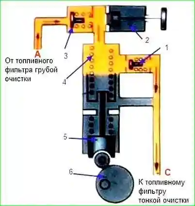
The fuel priming pump 16 (Fig. 1) is a piston type designed to supply fuel from the fuel tank through coarse and fine filters to the high pressure fuel pump.
The performance of the fuel priming pump is 3-4 times higher than the performance of the high pressure fuel pump, which guarantees the stability of the fuel supply process from cycle to cycle.
The pump device is shown in fig. 5.
The fuel priming pump is mounted with three bolts on the left side of the high pressure fuel pump housing and is driven from the camshaft eccentric through a roller follower.
Fuel priming pump: 1 - body: 2 - piston; 3 - piston spring; 4 - sealing washer; 5 - cork; 6 - stem bushing; 7 - pusher rod; 8 - pusher spring; 9 - piston pusher; 10 - pusher retaining ring; 11 - pusher cracker; 12 - roller axis; 13 - pusher roller; 14 - discharge valve; 15 - spring; 16 - sealing washer; 17 - cork; 18 - hand pump cylinder body; 19 - hand pump cylinder; 20 - hand pump piston; 21 - piston rod; 22 - handle; 23 - gasket: 24 - sleeve of the cylinder body; 25 - suction valve; 26 - valve seat
In the housing 1 (Fig. 6) of the pump, there is a piston 2, a spring 3 of the piston, resting against the piston on one side, and on the other side against the plug 5, suction 26 and discharge 13 valves, pressed against the seats 27 by springs 14.
The cavity of the pump housing, in which the piston moves, is connected by channels to the cavities above the suction and below the discharge valves.
The piston is driven by a pusher 8 through a rod 7. The pusher roller rotates on a floating axis 11, locked by two crackers 10 from longitudinal movement.
At the same time, pusher crackers, moving in the grooves of body 1, protect the pusher from turning. The rod 7 moves in the guide sleeve 6, which is screwed into the pump housing with a special adhesive.
Stem and sleeve are a precision pair.
To pump fuel when the engine is not running, the pump is equipped with a manual fuel priming pump.
This pump is used to remove air from the fuel system before starting the engine, as well as to fill the entire line with fuel during technical maintenance of the fuel equipment.