Crankshaft - steel, made by hot stamping.
All surfaces of the shaft are nitrided and the depth of the nitrided layer is at least 0.35 mm.
The crankshaft has five main bearings and four connecting rod journals.
The connecting rods are mounted on the crankpins (two for each).
The main and connecting rod journals are lubricated with oil under pressure during operation.
Oil is supplied to the main bearings, and then, through inclined channels to the crankpins.
The connecting rod journals have internal cavities closed with plugs, where the oil undergoes additional centrifugal cleaning.

To balance the engine and unload the main bearings from the inertial forces of the moving masses of the pistons and connecting rods and unbalanced centrifugal forces, counterweights are installed on the cheeks of the crankshaft, the assembly with which the shaft is balanced.
In addition, the balancing system includes two external masses, one of which is made in the form of a recess on the flywheel mounted on the rear end of the crankshaft, the other is a counterweight mounted on the front end of the crankshaft.
Axial fixation of the shaft is carried out by four bronze half rings installed in the undercuts of the rear main bearing.
To prevent rotation, the lower half rings with their grooves enter the pins pressed into the rear main bearing cover.
The toe and shank of the crankshaft are sealed with rubber self-clamping cuffs.
A crankshaft gear and a front counterweight are pressed onto the front end of the crankshaft, secured with a nut with a tightening torque of 176.4-294 Nm (18-30 kgcm).
The crankshaft of YaMZ-238BE2, YaMZ-238DE2 engines has a cone at the front end.
A hub is mounted on the cone, on which the liquid vibration damper and a pulley are fixed.
When repairing an engine, remember that impacts and dents on the vibration damper will damage it, which will inevitably lead to breakage of the crankshaft.
The extinguisher should only be stored and transported in a special container in a vertical position.
For YaMZ-238BE, YaMZ-238DE engines, a crankshaft 238BE-1005009 (marking 238N-1005015-U) is installed, and for engines YaMZ-238BE2, YaMZ-238DE2 - a crankshaft 238DK-1005009-30 (marking 238DK-10050 15 -30).
The crankshaft in forging is marked on the 5th cheek.
The crankshaft journals can be of two nominal sizes and therefore the following marking options and the use of the corresponding liners are possible.
238DK -1005015-30 or 238N -1005015-U:
- Diameter of main journals, mm - 110-0.022
- Main bearing markings - 236-1005170-B and 236-1005171-B;
- Main bearing thickness, mm - 2.965-0.012
- Crankpin diameter, mm - 88.00-0.022
- Marking of connecting rod bearing - 236-1004058-B;
- Conrod bearing thickness - 2.490-0.012
238DK -1005015-30 Sh1 or 238N - 1005015-U Sh1:
- Diameter of main journals, mm - 110-0.022
- Marking of main bearings - 236-1005170-B and 236-1005171-B;
- Main bearing thickness, mm - 2.965-0.012
- Crankpin diameter, mm - 87.75-0.022
- Marking of connecting rod bearing - 236-1004058-B;
- Conrod bearing thickness - 2.615-0.012
238DK -1005015-30 K1 or 238N -1005015-U K1
- Diameter of main journals, mm - 109.75-0.022
- Main bearing markings - 236-1005170-B P1 and 236-1005171-B P1
- Main bearing thickness, mm - 3.090-0.012
- Crankpin diameter, mm - 88.00-0.022
- Marking of the connecting rod bearing - P1 236-1004058-B
- Conrod bearing thickness - 2.490-0.012
238DK -1005015-30 Sh1K1 or 238N - 1005015-U Sh1K1:
- Diameter of main journals, mm - 109.75-0.022
- Main bearing markings - 236-1005170-B P1 and 236-1005171-B P1
- Main bearing thickness, mm - 3.090-0.012
- Crankpin diameter, mm - 87.75-0.022
- Connecting rod bearing marking - 236-1004058-B Р1
- Conrod bearing thickness - 2.615-0.012
Note: The letters "DK", "N", "U", "Sh", "K" and the numbers "30", "1" are branded when marking by impact.
Flywheel
The flywheel is cast in gray cast iron. The flywheel is marked in a recess on the non-working surface in the casting.
The following types of flywheels can be installed on engines:
- − 238-1005115-K (under the ring gear with module 4.25);
- − 238-1005115-N (under the ring gear with a modulus of 3.75).
These flywheels assemblies with ring gears are not interchangeable.
Flywheel 238-1005115-K (for ring gear with module 4.25) is installed with starter model 2501.3708-01, and flywheel 238-1005115-N (for ring gear with module 3.75) - with starter model 2501.3708- 21.
The flywheel is bolted to the crankshaft.
A high-hardness steel plate is installed under the bolts (one for all bolts).
The absence of self-loosening of the bolts is ensured by a tightening torque of 235-255 Nm (24-26 kgcm).
For precise fixation of the flywheel relative to the crankshaft journals, two pins are used, while the holes marked on the flywheel and on the plate must match the offset pin on the crankshaft.
The offset pin is located in the plane of the first crank.
The marking on the plate in the form of a dot must be on the outside.
Twelve radial holes in the flywheel are designed to rotate the crankshaft when adjusting the engine.
Access to the holes is possible with the flywheel housing lower hatch cover removed.
Crank
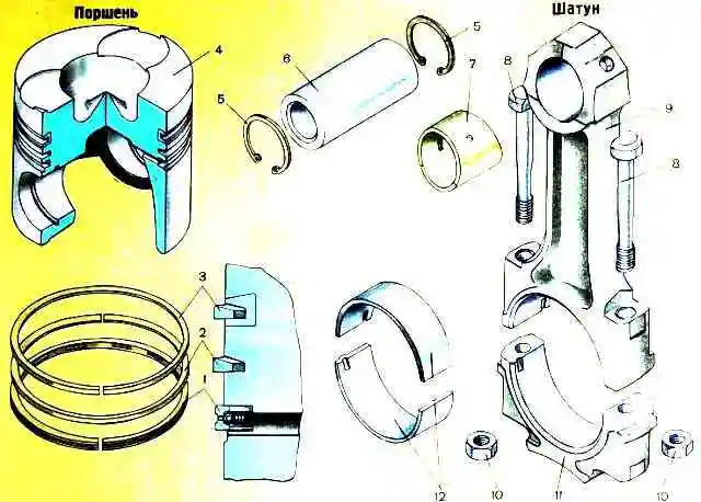
Connecting rod (Fig. 3) - steel, I-section, with an oblique connector of the lower head.
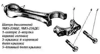
The connecting rod is finished assembled with the cap, so the caps are not interchangeable.
On the cover and the connecting rod, on the side of the short bolt, the serial number of the cylinder is stamped, and on the side of the long bolt, pairing marks are stamped in the form of a number that is the same for the connecting rod and the cover.
Replaceable liners are installed in the lower head of the connecting rod, and a steel-bronze bushing is pressed into the upper head.
The bushing is processed after being pressed into the connecting rod.
On YaMZ-238BE2, YaMZ-238DE2 engines, connecting rods 7511.1004045-02 (marking on the rod 7511.1004045) are installed, in which the distance between the axes of the holes in the upper and lower heads is increased by 15 mm, bevels on the upper head, the diameter is increased to 52 mm holes for the piston pin and there is no oil channel in the rod.
A steel-bronze bushing 7511.1004052-21 with an outer diameter of 56 mm is pressed into the upper head of the connecting rod.
On YaMZ-238BE, YaMZ-238DE engines, connecting rods 236-1004045-B3 (marking 236-1004045-B2) with an oil channel in the rod are installed.
A steel-bronze bushing 840.1006026-10 with an outer diameter of 54 mm is pressed into the upper head of the connecting rod.
Inserts
The main bearing shells of the crankshaft and the lower head of the connecting rod (Fig. 4) are replaceable, thin-walled, have a steel base and a working layer of lead bronze.
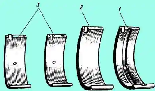
The upper and lower crankshaft main bearing shells are not interchangeable. The top liner has a hole for oil supply and a groove for its distribution.
The connecting rod bearings are interchangeable.
On engines YaMZ-238BE, YaMZ-238DE, oil is supplied through the hole in the liner to the bushing of the upper head of the connecting rod and the piston pin.
Cleaning the crankpin cavities
Each time the crankshaft is removed from the engine, clean the cavities of the connecting rod journals, after removing the plugs 2 (Fig. 4), which close the cavities.
Replace the caps with new ones, they are not allowed to be reused.
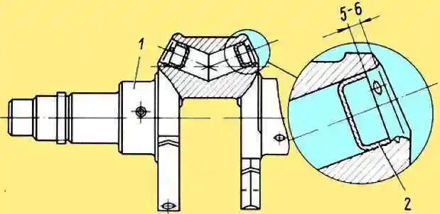
Before installing the plugs, saw down the swelling of the metal at the edges of the holes from the previous centering, rinse the shaft and blow out the oil channels.
Press the plugs to a depth of 5–6 mm from the edge of the hole, then punch inside the hole at three equally spaced points around the circumference, to prevent spontaneous extrusion of the plugs.
Installing the crankshaft on the engine
When installing the crankshaft on the engine, ensure that the dimensions of the bearing shells correspond to the dimensions of the shaft journals (see table).
Before installation, ensure that the external surfaces and internal cavities of the crankshaft and other mating surfaces are clean.
Lubricate the journals and running surfaces with clean engine oil.
To facilitate the installation of the flywheel in the correct position relative to the crankshaft, the number "8" is applied to the hub of the flywheel for eight-cylinder engines, which, when assembled, must be combined with the number "2" on the end of the crankshaft.
Main bearing caps are not interchangeable; when installing them, make sure that the stamp on the cover matches the stamp on the block.
Tighten the main bearing caps starting with the vertical bolts and tighten in two steps with a torque after retorque of 430-470 Nm (43-47 kgf m), then tighten the horizontal bolts in two steps with a final tightening torque of 90-120 Nm (9-12 kgf m).
Before tightening the rear thrust main bearing, equalize the axial clearance, for which, after slightly tightening the bearing cover with bolts, move the crankshaft back and forth in the axial direction until it stops with a crowbar, first forward, then back, aligning the position of the cover.
After tightening the bolts, check the end play with a feeler gauge. It should be the same on both sides of the lid.
Replacing the crankshaft gear
The crankshaft gear can be replaced without removing the crankshaft from the engine.
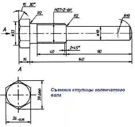
Remove the drive pulley. To remove the hub with pulley and damper from the tapered end of the eight-cylinder crankshaft, use the puller shown in Figure 6.
With the pulley and the front cover of the block removed, press the front counterweight and gear with a puller.
Before installing, heat the gear and the front counterweight to a temperature of 105-155ºС and successively press them in until they stop using a special tool.
Steel 40X GOST 4543-71 Harden, temper 34-39 HRC