The power system consists of a fuel tank, fuel lines, a fuel pump, a sump filter, a fine fuel filter, a carburetor with throttle and air damper drives, and an air filter
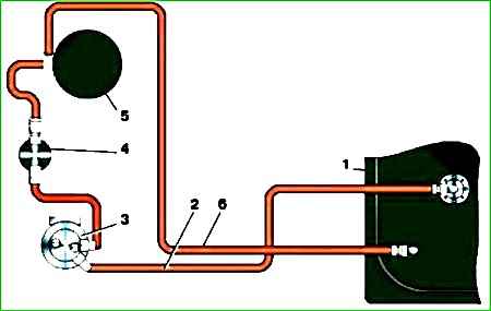
The fuel tank is metal, with a filling capacity of 70 liters, located on the left side on the frame side member.
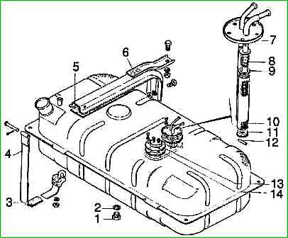
The tank is attached to the spar using brackets, tie strips and hooks. Cardboard spacers are installed between the brackets, tapes and the tank.
At the top of the tank there is a fuel intake, consisting of a tube and a filter in the form of a brass mesh, as well as a sensor for the electric fuel level indicator.
There is a drain plug at the bottom of the tank.

The air filter is a dry type, with a replaceable filter element made of porous cardboard, installed on the carburetor through a rubber gasket.
To reduce air intake noise, the filter is equipped with an air intake corrugated hose connected to a metal pipe located on the right side of the mudguard.
When the ambient air temperature is below 5° C, to supply heated air to the carburetor, the air intake hose must be disconnected from the branch pipe located on the mudguard and connected to the screen branch pipe installed on the engine exhaust pipe.
It is necessary to use filter elements with the following designations: 3102-1109013-02 (-03-04-05,-06) or 31029-1109013 (-01-02,-0З)
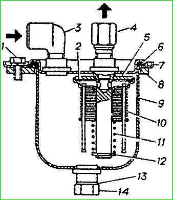
The B-9V fuel pump is a diaphragm type, driven by an eccentric located on the engine camshaft.
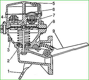
The fuel pump consists of a housing assembly with a diaphragm 8 and a drive lever 9, a head with valves 4 and 7, and a cover.
A diaphragm of four petals made of varnished fabric is clamped between the housing and the pump head.
The diaphragm rod is sealed with rubber seal 2.
The valve consists of a holder made of zinc alloy, a rubber valve and a brass rod, pressed by a spring (made of bronze wire).
A filter 6 made of fine brass mesh is installed above the suction valves of the pump.
To fill the carburetor with fuel when the engine is not running, the pump has a device for manual drive.
To control the tightness of the diaphragm, there is a hole in the pump housing with a mesh filter 3.
The K-151 carburetor consists of three main detachable parts, connected through sealing gaskets with screws.
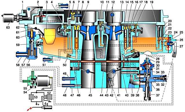
K-151 carburetor diagram: 1 – cover; 2 – valve for unbalancing the float chamber (only K-151V); 3 – float; 4 – air jet of the secondary chamber transition system; 5 – fuel jet of the secondary chamber transition system; 6 – threaded screw holder for econostat sprayer; 7 – main air jet of the secondary chamber; 8 – econostat sprayer; 9 – emulsion tube of the main dosing system of the secondary chamber; 10 – accelerator pump nozzle holder with discharge valve; 11 – accelerator pump nozzle; 12 – air damper; 13 – plug-in small diffuser of the secondary chamber with a spray; 14 – main air jet of the primary chamber; 15 – emulsion tube of the main dosing system of the primary chamber; 16 – block of fuel and idle air jets with an emulsion tube; 17 – emulsion jet of the idle system; 18 – second idle air jet; 19 – adjusting needle on the accelerator pump drainage channel nozzle; 20 – travel limiter of the suction ball valve of the accelerator pump; 21 – carburetor body; 22 – bypass (drainage) jet of the accelerator pump; 23 – ball of the suction valve of the accelerator pump; 24 – spring for the suction stroke of the accelerator pump diaphragm; 25 – accelerator pump diaphragm; 26 – accelerator pump diaphragm cover; 27 – accelerator pump drive lever; 28 – main fuel jet of the primary chamber; 29 – fitting of the EPHH valve; 30 – EPHH valve diaphragm; 31 – shut-off valve EPHH; 32 – plug-in plastic screw rotation limiter of “quality”; 33 – screw for adjusting the mixture composition (“quality screw”) at idle; 34 – relief sub-diaphragm hole in the EPHH valve body; 35 – forced idling economizer housing (idling unit); 36 – hole of the adjustable air valve of the idle system; 37 – screw for adjusting the crankshaft speed at idle speed; 38 – gasket for idle speed unit; 39 – additional screw for adjusting the mixture composition on the main idle fuel supply branch (only on early modifications of carburetors); 40 – transition slot hole of the idle system; 41 – throttle valve of the primary chamber; 42 – accelerator pump lever drive cam; 43 – accelerator pump lever roller; 44 – inlet window of the air channel of the idle system; 45 – throttle valve of the secondary chamber; 46 – thermal insulating gasket of the carburetor body; 47 – throttle body; 48 – vacuum sampling fitting to the electromagnetic control valve EPHH; 49 – vacuum tap to the vacuum ignition timing regulator; 50 – main fuel jet of the secondary chamber; 51 – vacuum tap to the exhaust gas recirculation valve; 52 – power circuit of the EPHH control unit; 53 – circuit of the EPHH control microswitch; 54 – filter on the ventilation fitting of the electromagnetic control valve EPHH; 55 – electromagnetic control valve EPHH; 56 – screw securing the fuel fittings of the float chamber; 57 – fuel filter; 58 – fuel fitting; 59 – plug on the wall of the float chamber; 60 – shut-off valve of the float mechanism; 61 – locking needle earring; 62 – float tongue; 63 – electromagnet of the float chamber unbalance valve drive (only on K-151V carburetors)
The upper part - the carburetor cover includes an air pipe, divided into two channels, with an air damper in the channel of the first chamber.
The middle part consists of a float and two mixing chambers and is the carburetor body. The lower part - the throttle body includes mixing pipes with the throttle valves of the first and second carburetor chambers.
The gasket between the middle and lower parts of the carburetor is sealing and heat-insulating.
Structurally, the carburetor consists of two mixing chambers - the first and second. Each of the carburetor chambers has its own main metering system.
Idle system - with quantitative regulation of constant mixture composition (autonomous idle system).
In the second chamber of the carburetor there is a transition system with fuel supplied directly from the float chamber, which comes into operation when the throttle valve of the second chamber is opened.
The accelerator pump is diaphragm type. to enrich the combustible mixture at At full load, an econostat is provided in the second chamber.
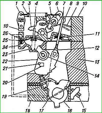
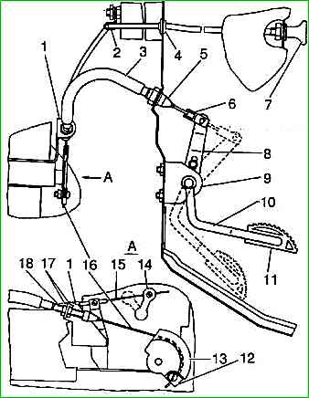
Diagram of a semi-automatic start-up and warm-up device: 1, 5, 6, 16 - levers; 2 - starting spring; 3 - intermediate lever; 4 - pneumatic corrector rod; 7 - traction; 8 - sector lever; 9 - air damper; 10 - carburetor cover; 11 - sealing element; 12 - adjusting coupling; 13 - float chamber body; 14 - air damper drive lever; 15 - thrust screw of the throttle valve of the primary section of the carburetor; 17 - throttle valve of the primary section of the carburetor; 18 - mixing chamber housing; 19 - screw with roller; 20 - emphasis; 21 - pin; 22 - profile lever; 23 - pneumatic corrector spring; 24 - pneumatic corrector cover
When the accelerator pedal is released, the contacts of microswitch 35 must be open.
The fuel shut-off system works as follows.
When the accelerator pedal -1 is released and the engine crankshaft speed is more than 1400, the control unit does not supply voltage to the solenoid valve, as a result, through the channels of the solenoid valve, atmospheric air enters the forced idle economizer, the valve of which closes the idle channel.
In the event of a malfunction of the fuel shut-off system (the engine does not start or “stalls” when the throttle pedal is released), you must first make sure that the electrical contacts of the system elements are reliable, after which you should sequentially check the functionality of the solenoid valve, microswitch and control unit .
To check the solenoid valve and microswitch, you need to disconnect the electrical connector of the control unit, turn on the ignition (do not start the engine!) and in the engine compartment, smoothly open and close the carburetor throttle valves several times with one hand, and hold the solenoid valve with the other.
If the solenoid valve and fuse are working properly and if the microswitch is working properly and correctly adjusted, you should feel the activation of the solenoid valve (vibration, clicks).
To check the control unit, you need to insert the connector into the unit, turn on the ignition, start the engine and warm it up.
Then, from the engine compartment side, open the throttle valves approximately 1/3 of the way with one hand, and hold the solenoid valve with the other.
Release the throttle valves sharply. In this case, if the control unit is corrected, the solenoid valve should turn off, and when the crankshaft speed decreases to approximately 1050, the solenoid valve should turn on.
All carburetor systems are connected to a float chamber, the fuel level in which is maintained by float 2 and fuel valve 1.
")

")
")
")
")
")
")
")