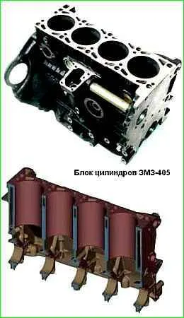
The cylinder block is cast from gray cast iron and is made in the form of a monoblock with the crankcase part lowered below the axis of the crankshaft.
Between the cylinders in the upper part there are ducts made in the casting for the passage of coolant
There are five main bearing housings located at the bottom of the block.
The main bearing caps, made of high-strength cast iron, are machined together with the cylinder block and therefore are not interchangeable.
On the lower surfaces of the 1st, 2nd and 4th covers their numbers are stamped for correct installation. When installing covers, the locking grooves for the liners in the cylinder block and in the covers should be located on one side.
Blocks with holes on the cylinder walls, cracks on the upper plane of the block and on the ribs supporting the main bearings, with holes on the water jacket and crankcase are subject to rejection.
As a result of natural wear, the cylinders in the block acquire the shape of an irregular cone in length and an oval in circumference.
Wear reaches its greatest value in the upper part of the cylinders against the upper compression ring, with the piston position at TDC, the smallest in the lower part, with the piston position at BDC.
Cylinders and pistons are divided into five size groups A, B, C, D, E. The letter indicating the cylinder group is painted on the left outer side of the block opposite each cylinder.
All cylinders in one block should, as a rule, be processed to the same repair size with a tolerance of +0.036...+0.072 mm from the nominal value, with the exception of cases when it is necessary to remove shallow scratches on the cylinder mirror (within the magnification range cylinder diameter by 0.10 mm), here only defective cylinders can be corrected.
Where only a limited number of pistons are available, it is recommended to calculate the nominal diameter for each cylinder based on the actual size of the piston skirt diameter intended to operate in that cylinder, and machine the cylinders to that size within the machining tolerance specified below .
Deviations from the geometrically correct shape of the cylinders must be located within the tolerance range of the size group for the diameter of the cylinder.
The tightness of the cooling jacket is checked using the pressure test method. To do this, you need to plug all the holes in the block, except for one, to which compressed air is supplied.
The block is lowered into a bath of water and compressed air is supplied at a pressure of 1.5 atm. Air bubbles will appear in damaged areas.
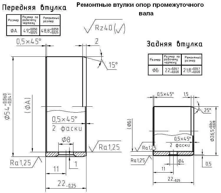
Repair of intermediate shaft support bushings consists of replacing them with standard or repair ones of increased thickness, depending on the wear of the mounting holes in the cylinder block, and then boring the inner hole of the bushings to a standard or repair size, depending on the wear of the intermediate shaft support journals.
Make repair bushings from anti-friction alloy.
Replace standard bushings with repair ones also if their fit is loosened or rotated.
Before installing the intermediate shaft supports, remove the tube. When installing repair bushings, ensure that the holes in the oil channels match.
Bore the intermediate shaft supports in one installation to ensure alignment. Press the new tube onto anaerobic sealant.
The intermediate shaft journals are ground to a repair size in case of wear exceeding the maximum allowable.
If the holes for the oil pump drive are worn beyond the acceptable level, bore the holes to the repair size for repair bushings.
Make repair bushings from gray cast iron with an outer diameter of 21 mm and length: lower - 17 mm, upper - 30 mm.
Press in the repair bushings, drill in the upper bushing through a hole with a conical thread a through hole for oil supply Ø 3.5 mm, entering the oil line of the cylinder block, and process the holes in the bushings to the nominal size.
Machine the mounting holes of the cylinder block for the bushings and the bushing holes in one installation.
Damage to threaded holes, in the form of nicks or thread breakage of less than two threads, is restored by running the threads with a normal-sized tap.
Threaded holes that have worn or broken threads of more than two threads are repaired by cutting threads of an increased repair size, installing threaded screws and then cutting them into normal threads size or installing threaded spiral inserts, the latter repair method is the most effective and less labor-intensive.
Controlled parameters when repairing the cylinder block, pistons, connecting rods and intermediate shaft:
Cylinder diameter:
- - nominal size Ø 95.5+0.072+0.036 mm;
- - maximum permissible size 95.65 mm;
- - first repair size +0.25 mm;
- - second repair size +0.5 mm
Pistons diameter:
- - nominal size Ø 95.5+0.024−0.012 mm;
- - maximum permissible size 95.4 mm;
- - first repair size +0.25 mm;
- - second repair size +0.5 mm
Gap between piston and cylinder (selection):
- - nominal size 0.036-0.060 mm;
- - maximum permissible size 0.25 mm;
Increase for repair sizes of cylinders, pistons, piston rings:
- - first repair size 0.25;
- - second repair size 0.5
Width of grooves for compression rings:
- - upper, nominal size - 1.55±0.01 mm, maximum permissible - 1.58 mm;
- - lower, nominal size - 1.8±0.01 mm, maximum permissible - 1.83 mm
The height gap between the groove and the compression ring is nominal size - 0.045...0.090 mm, maximum permissible - 0.15 mm;
The height gap between the groove and the oil scraper ring is nominal size - 0.045...0.090 mm, maximum permissible - 0.15 mm;
The diameter of the cylinder block supports for the main bearing shells is nominal size - 67+0.019 mm, maximum permissible - 67.03 mm;
Radial runout of the middle supports of the cylinder block relative to the outer ones: nominal size - 0.02 mm; maximum permissible - 0.05 mm;
Width of the third support of the cylinder block: nominal size - 29−0.060−0.120 mm; maximum permissible size - 22.1 mm;
Diameter of the inner bushings of the intermediate shaft supports:
- - front bushing nominal size - 49+0.050 mm; maximum permissible size - 49.1 mm; repair size -0.2 mm;
- - rear bushing nominal size - 22+0.041+0.020 mm; maximum permissible size - 22.1 mm, repair size -0.2 mm;
Diameter of intermediate shaft journals:
- - front neck nominal size - 49−0.016−0.013 mm; maximum permissible size - 48.95 mm, repair size -0.2 mm;
- - rear neck nominal size - 22−0.013 mm; maximum permissible size - 21.95 mm; repair size -0.2 mm;
Diameter of cylinder block holes for intermediate shaft bushings:
- - front bushing nominal size - Ø 52.5+0.03 mm; maximum permissible size - 52.56 mm, repair size - +1.5 mm;
- - rear bushing nominal size - Ø 25+0.021 mm; maximum permissible size - 25.06; repair size - +1.5 mm;
Diameter of the hole for the oil pump drive shaft: nominal size Ø17+0.060+0.033; maximum permissible size - 17.1 mm; repair size Ø21+0.033 mm;
Diameter of the connecting rod crank head: nominal size 60+0.019 mm; maximum permissible size 60.03 mm
Nonparallelism of the axes of the holes of the piston and crank heads of the connecting rod in two mutually perpendicular planes: nominal size 0.04 mm over a length of 100 mm; maximum permissible - 0.06 mm;
Diameter of the connecting rod hole for the bushing: nominal size Ø 23.25+0.045 mm; maximum permissible Ø23.30 mm;
Diameter of the connecting rod bushing hole for the pin: nominal size 22+0.07−0.003 mm; maximum permissible 22.01 mm
*tolerance 0.036 mm is divided into 3 groups - every 0.012 mm
* tolerance of 0.010 mm is divided into 4 size groups - 0.0025 mm each