In a car cabin with three rows of seats, an additional heater is located on the floor behind the passenger seat (or under it)
In buses, the additional heater is installed on the floor under the seat in the front part of the passenger compartment
The additional heater operates in internal air mode.
Repeated passage of internal air through the heater radiator provides high intensity heating of the cabin (interior).
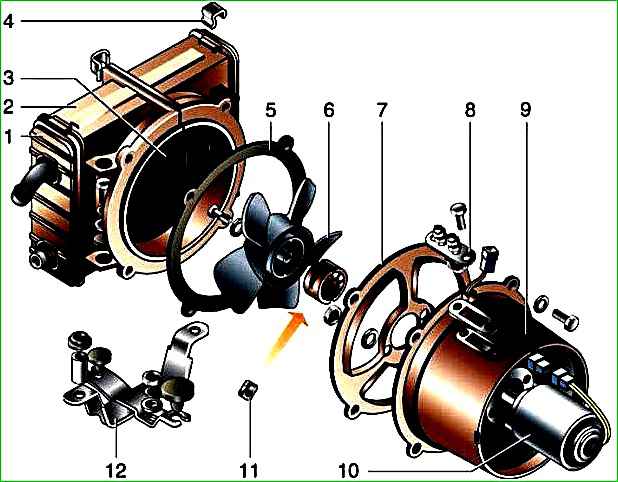
The design of the additional heater is shown in the figure.
In the heating system of these vehicles, an electric pump is used, which increases the fluid flow in the system, which improves the heating of the cabin (interior).
Removing the auxiliary heater fan motor

Use a slotted screwdriver to unscrew the two screws securing the auxiliary heater guard.

Remove the fence.

Disconnect the plug block from the heater motor.

Using a wrench or socket “7”, unscrew the two nuts securing the wires and disconnect them from the terminals of the electric motor resistor.

Holding the bolts securing the electric motor cap from turning with a 10mm wrench, use the same wrench to unscrew the four nuts

Remove the cap together with the electric motor

There is a rubber O-ring installed between the cap and the heater casing.

Remove the electric fan from the hood.

Use a screwdriver to unscrew two screws

Remove the impeller from the electric motor shaft.

Use an 8 wrench to unscrew the two fastening nuts

Remove the motor flange and the rubber sealing gasket.

Use a 10mm wrench to unscrew the two fastening bolts

Remove the electric motor resistor
Having replaced the faulty parts, we assemble and install the electric fan in the reverse order.
Removing the auxiliary heater radiator
Drain the coolant
Remove the electric fan.

Using a screwdriver and loosening the clamps, remove the hoses from the radiator pipes of the auxiliary heater

Using a 12mm wrench, unscrew the two bolts securing the radiator casing to the bracket.

Remove the auxiliary heater radiator with casing.

It is attached to the bracket through rubber washers and steel bushings

Use a screwdriver to “snap off” the two fastening brackets

Remove the casing cover

Remove the second cover in the same way.

“Snap off” two more fastening brackets

Having separated the halves of the heater housing, we remove the radiator from it.

When replacing a radiator with a 19mm wrench, unscrew the plastic pipes from it and, if necessary, replace them with a new radiator
Install the radiator in reverse order, and then fill the cooling system with liquid.