Checking and adjusting wheel alignment angles is necessary to ensure good stability and controllability of the vehicle and uniform tire wear during its operation
Checking and adjusting wheel alignment angles is carried out on special stands in accordance with their operating instructions.
The discrepancy between the actual values measured on the vehicle and the control values indicated below is due to wear and deformation of suspension parts, and deformation of the body.
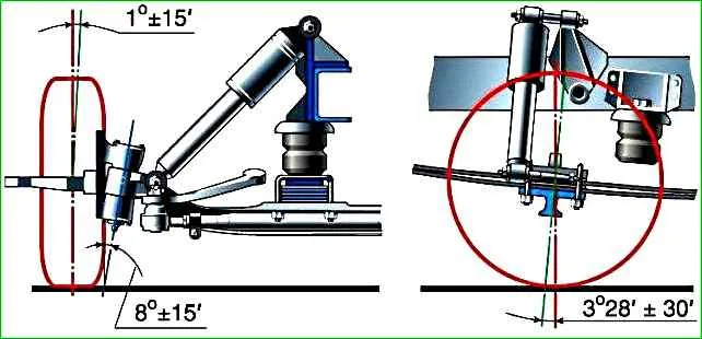
The angle of inclination of the kingpins back is provided for by the design of the front axle and is not adjustable.
As the load on the vehicle increases, the rearward angle of the kingpins increases due to the deflection of the springs.
For a loaded vehicle, this angle is 3°30'±30'.
The difference in the angles of inclination of the left and right kingpins should not exceed 30'.
During the operation of the vehicle, the rearward angle of the kingpins may change due to deflection or twisting of the beam, breakage or significant settlement of the front springs, wear of the kingpins, bushings, etc.
To restore the normal backward angle of the kingpins, replace any deformed or worn parts.
In rare cases, when replacing parts does not completely eliminate the angle deviation, use a steel wedge inserted between the spring pad and the front axle beam pad.
If spacers are used, they must be securely attached to the beam.
The wheel camber is not adjusted; it is ensured by tilting the steering knuckle spindle within 1°±15' to the road plane.

During vehicle operation, the camber angle may change due to deflection of the front axle beam or steering knuckle spindle. Check the camber angle with instruments.
If you don’t have the necessary instruments, then, using a square, measure the distance from the top “III” and bottom “IV” points of the rim to the vertical plane.
The difference in these dimensions at the correct camber angle should be within 4 -7 mm.
To restore the required camber angle value, find out the reason that caused the camber change.
Often such reasons are wear of the kingpins and their bushings, insufficient tightening of the front wheel hub bearings, and deformation of the front axle beam.
The lateral inclination of the kingpins from the vertical is 8°. It is not regulated during operation.
Deviations from the normal value of this angle may be caused by a bent front axle beam.
To restore the required angle, straighten the beam.
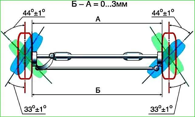
Adjusting the toe of the front wheels
The amount of toe-in of the front wheels is determined by the difference in size between the inner side surfaces of the tires at the level of the wheel axis.
This difference should be from 0 to 3 mm.
The wheels must be in the direction of straight-line movement.
Place the car on a flat horizontal platform.
If there is no special ruler, you can measure the difference in distances between the wheels using a 1.5 m long rod and a caliper depth gauge.

Start measuring from the front side of the wheel axle.
For greater accuracy, mark with chalk the places on the tires between which the distance was measured.
Roll the car forward so that the wheels rotate 180° and repeat the measurement between the points, but now behind the wheel axle.

If the toe-in value differs from the norm, then use two 17mm wrenches to loosen the tightening of both clamps of the transverse steering rod.

By rotating the rod, set the amount of toe. If the rod does not turn, treat the threads of the tie rod ends with penetrating fluid
Check the amount of toe-in and, if necessary, repeat the adjustment.
At the end of the work, tighten the clamp bolts.
")

")
")
")
")
")
")
")