Before you begin troubleshooting any electrical circuit, carefully study the corresponding diagram in order to understand its functionality as clearly as possible
The scope of troubleshooting is usually narrowed by gradually identifying and eliminating normally functioning elements of the same circuit.
If several elements or circuits fail at the same time, the most likely cause of failure is a blown corresponding fuse or a loss of contact with ground (different circuits in many cases can be shorted to one fuse or ground terminal).
Electrical equipment failures are often explained by simple reasons, such as corrosion of connector contacts, failure of a fuse, burnt-out fuse link or damaged relay.
Visually check the condition of all fuses, wiring and connectors on the circuit before proceeding with a more detailed check of the serviceability of its components.
When using diagnostic tools for troubleshooting, carefully plan (in accordance with the supplied electrical diagrams) at which points in the circuit and in what sequence the device should be connected to most effectively identify the fault.
Checking indicators and sensors of cars produced before 2003
Oil pressure indicator
To check the oil pressure gauge 23.3829, remove the instrument cluster - "How to remove and install the instrument cluster of a Gazelle car"
Assembling the circuit
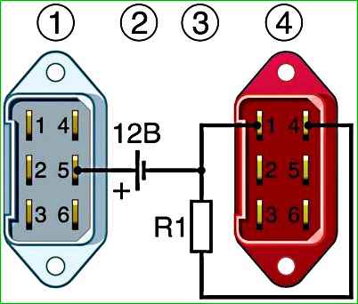
With a resistor resistance of 300 Ohms, the instrument needle should be at the zero mark of the scale, and with a resistance of 180 Ohms - at the beginning of the green zone.
With a resistance of 68 Ohms, the instrument needle should move to the beginning of the red zone.
Additionally, an emergency oil pressure sensor is installed in the cylinder head, which should open its contacts at a pressure of 40–80 kPa (0.4–0.8 kgf/cm 2).
Coolant temperature gauge
The coolant temperature gauge 37.3807 works in conjunction with the temperature sensor TM-106-10, screwed into the cylinder head.
The sensor has a thermistor (a resistor that changes its resistance depending on temperature).
You can check the sensor with an ohmmeter. A working sensor at a liquid temperature of 20–25 °C (temperature indicator arrow at the beginning of the scale) should have a resistance of 1400-1900 Ohms, and at 80 °C (arrow on the border of the green and white zones) - 100-110 Ohms.
The sensor is non-separable and cannot be repaired.
Removing the temperature sensor for engines type ZMZ-402
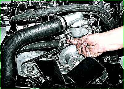
1. Disconnect the wire from the temperature indicator sensor output
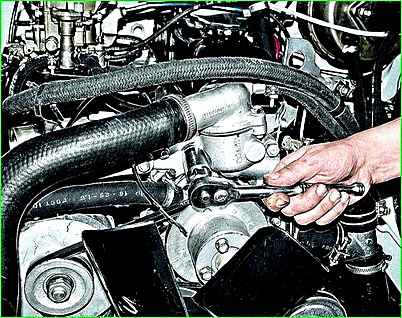
2. Use a 21mm head to unscrew the sensor
Removing the temperature sensor for engines type ZMZ-405, ZMZ-406
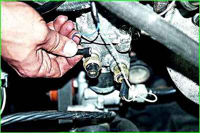
1. Disconnect the connector block from the sensor output
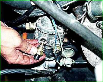
2. Using a 21 key, unscrew the sensor from the thermostat housing.
Remove the sensor.
To check the temperature gauge, we remove the instrument cluster, article - “How to remove and install the instrument cluster of a Gazelle car”
Assemble the circuit shown in the figure.
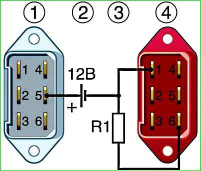
With a resistor resistance of 68 Ohms, the instrument needle should be in the middle of the red zone, at 180 Ohms - at the beginning of the green zone, and at 910 Ohms - at the beginning of the white zone.
A TM 111-02 sensor is additionally installed in the cylinder head to indicate coolant overheating.
The sensor should operate at a liquid temperature of 104 – 109 °C.
Fuel level indicator
Fuel level indicator 32.3806 works in conjunction with sensor 5412.3827 installed in the fuel tank.
The sensor is a rheostat with a resistor made of nichrome wire.
The movable contact of the rheostat is moved by a lever with a float.
At the end of the lever there is an additional contact that closes the control lamp circuit when there is a reserve fuel supply in the tank.
The serviceability of the fuel gauge sensor can be checked with an ohmmeter.
We replace the faulty sensor.
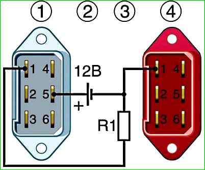
To check the fuel level indicator, remove the instrument cluster.
Consistently changing the resistance, we test the pointer.
With a resistance of 330 Ohms, the device should show an empty tank, with 118 Ohms - half a tank, and with 11 Ohms - a full tank.
Data for checking the fuel level sensor
Amount of fuel in tank - Resistance (Ohm):
- - empty tank - 315-345;
- - half tank - 108-128;
- - full tank - 6-16
Voltmeter
The voltmeter can be checked by comparing its readings with the readings of a conventional tester used by radio amateurs.
Before testing, we recommend holding the voltmeter at 12 V for about 5 minutes.
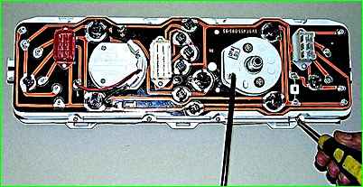
Failed control devices - we replace them by unscrewing eight screws with a slotted screwdriver
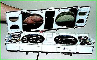
Remove the frame with glass
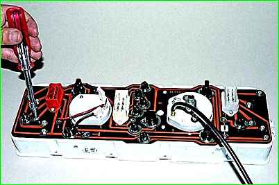
Use a 5.5 socket to unscrew the nuts securing the faulty control device.
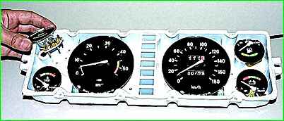
Remove the device
We install the new device in the instrument cluster in the reverse order.


