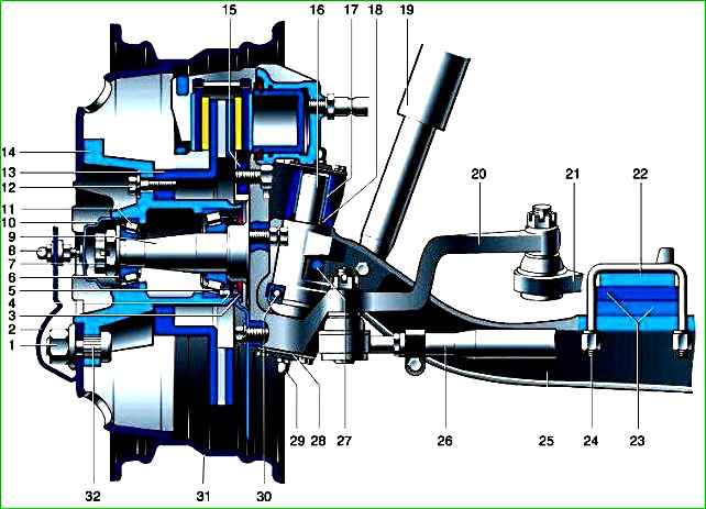
The front suspension consists of a stamped I-beam connected to the steering knuckles using pins
The pins have a flat in the center and are locked in the beam holes with wedge stops.
Vertical loads from the steering knuckles are transmitted to the beam by thrust ball bearings, protected from dirt by rubber-metal caps.

The upper bosses of the steering knuckles have annular grooves in which rubber sealing rings are installed, protecting the friction surfaces of the bushings and pins from dirt.
The pivot holes in the steering knuckle bosses are covered with covers with gaskets.
To lubricate the pin bushings, grease nipples are installed in the center of the covers.
The support bearings of the pins are lubricated simultaneously with the lubrication of the lower bushings.
For the passage of lubricant, spiral grooves are made in the bushings of the steering knuckles.
The steering knuckles consist of two parts - a flange and a pin pressed into it.
The front wheel hubs are mounted on axles on two tapered roller bearings. The tightening of the bearings is adjusted with a nut.
The steering linkage is located behind the front axle beam.
The trapezoid arms are attached to the steering knuckles with bolts. During assembly, their threads are coated with a sealant that prevents them from unscrewing during operation.
Limitation of the angles of rotation of the steering wheels is ensured by bolts screwed into the flanges of the steering knuckles.
The longitudinal steering rod is solid-forged, transverse, tubular, with threaded ends.
The tips have different thread directions, which allows you to adjust the toe-in of the wheels without removing traction from the car.
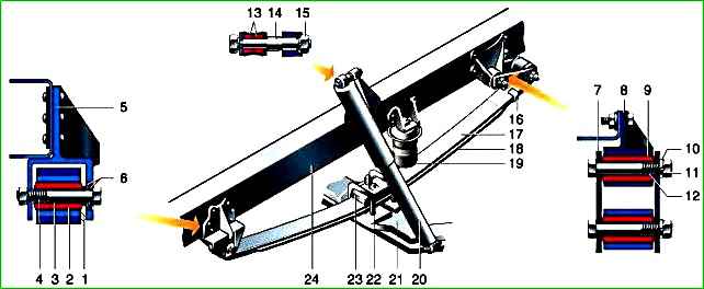
The suspension is made on longitudinal leaf springs with two hydraulic shock absorbers.

The suspension can use small-leaf or multi-leaf springs. A leaf spring consists of two sheets held together by a clamp and a center bolt.
A multi-leaf spring has four leaves.
The spring is attached to the frame brackets through lugs formed by the bent ends of the sheets, with the front lug formed by two sheets, and the rear one only by the top (root) sheet.
The rear eye is attached to the spar through an earring that compensates for changes in the distance between the ends of the spring during suspension operation.
All moving connections: front and rear spring mounts, shackle mounts, upper and lower shock absorber mounts are made on rubber bushings.
The spring is attached to the bridge beam with stepladders through the overlay.
4x4 vehicles have springs consisting of five leaves.
To limit the upward travel of the suspension, a rubber buffer is installed above the spring.
Telescopic shock absorbers, two-pipe, collapsible.
They are attached with the lower end (reservoir) to the bridge beam, and with the upper end (rod) to the frame spar bracket.
Front suspension malfunctions, causes and solutions
Knock in the front suspension
Wear of the king pin and bushings (sliding bearings) - Replace the king pin and bushings (see article - “How to check and replace the king pin and bushings”
Large axial play of the steering knuckle on the king pin - Install a shim or replace the thrust bearing
The front hub bearings are not adjusted or have failed - Adjusted repair or replace bearings
Loosening the shock absorber - Tighten the threaded connections
Wear of the upper and lower shock absorber bushings - Replace the bushings
Reduced efficiency of the front shock absorber
Fluid leakage from the front shock absorber - Tighten the shock absorber reservoir nut or replace the shock absorber (see article - "How to replace shock absorbers on car suspensions"
Uneven wear of the tire tread pattern
Increased play in wheel bearings - Adjust bearing tightness
The wheels are not balanced - Balance the wheels
Pin and bushings are worn - Replace the king pin and bushings
Frequent “breakdowns” when driving on uneven roads
Settlement or breakage of springs - Replace the springs (see article - “How to remove, disassemble and reassemble the front spring of a car”
Long-term operation of an overloaded vehicle - Same
Loss of elasticity or destruction of the compression buffer - Replace the compression stroke buffer
Car roll
Settlement of one spring or breakage of spring leaves - Replace the spring or defective leaves
Displacement of the front wheel track relative to the rear wheels during straight-line movement
Breakage of the main leaf of one of the springs - Replace the spring or main leaf
Breakage of the center pinch bolt of one of the springs - Replace the center pinch bolt


