To remove the engine, the car must be placed on a viewing hole. The workplace must be equipped with a hoist or other lifting device with a load capacity of at least 300 kg
Remove the engine in the following order:
- - open the hood and remove it by unscrewing the four bolts securing it to the hinges;
- - drain the coolant from the cooling system by unscrewing the cap on the radiator and opening the taps on the cylinder block and heater. Remove the expansion tank plug;
- - drain the oil from the engine crankcase and gearbox by unscrewing the drain plugs. After draining the oil, replace the plugs and tighten them tightly;
- - remove the battery;
- - hook the engine to the cargo eyes and tighten the hoist chain.
- Disconnect the fuel supply and drain lines
- Remove the battery.
- Remove the hood.
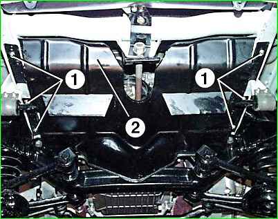
- Unscrew the six bolts 1 and remove the front engine mudguard 2.
- Drain the engine cooling system.
- Drain the oil from the engine crankcase.
- Drain the oil from the gearbox.
- Remove the cooling system radiator with electric fan and fan shroud.
- Remove the ignition coils.
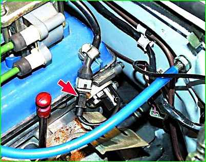
Disconnect the phase sensor connector from the wiring harness.
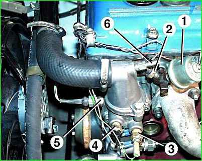
Unscrew the screws and disconnect the wires from the oil pressure indicator 1 and emergency oil pressure 2 sensors.
Disconnect the connectors from the engine temperature sensors 5, coolant temperature indicator 4, coolant overheat indicator 3.
Loosen the clamp and remove the hose to the expansion tank from fitting 6 of the thermostat.
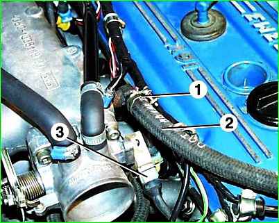
Loosen the tightening of clamp 1 and remove hose 2 from the fitting to the check valve of the vacuum brake booster.
Disconnect connector 3 from the throttle position sensor.
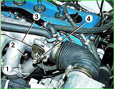
Unscrew nut 1 and remove the blue ground wire from the stud at the front end of the receiver.
Unscrew nut 4 and pull out accelerator cable 3 from the air throttle valve drive sector.
Disconnect plug block 2 from the wiring harness, located between the engine intake pipes, the speed sensor and the crankshaft synchronization sensor installed near the crankshaft pulley ring gear.
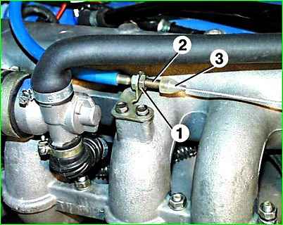
Move the cable gland 3 from the threaded end 2 of the cable shell, unscrew the nut 1 securing the cable end and pull out the end 2 from the bracket fixed to the engine intake pipe, sliding it back.
Then remove the accelerator cable from the bracket upwards.
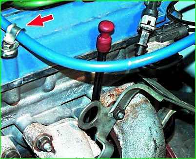
Bend the accelerator cable holder and remove the cable from it.
Move the accelerator cable away from the engine.
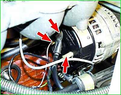
Disconnect the wires from the generator.
When disconnecting the plugs, it is advisable to mark them so as not to confuse them.
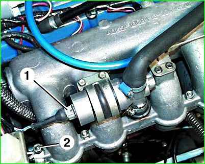
Disconnect connector 1 from the idle speed control.
Unscrew nut 2 and remove the ground wires from the stud at the rear end of the receiver
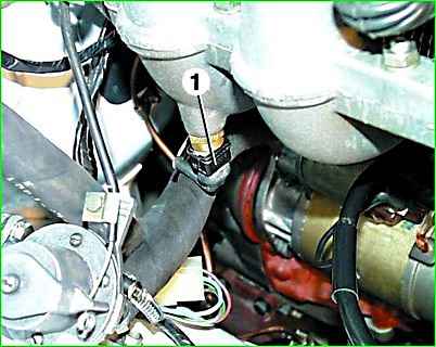
Disconnect connector 1 from the air temperature sensor.
Loosen clamp 2 and remove the coolant supply hose from the heater tap fitting.
Disconnect the wires from the starter.
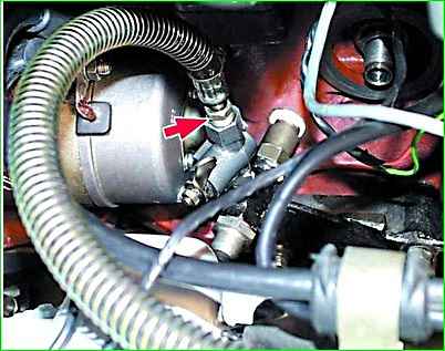
Unscrew the nut and disconnect the oil supply hose to the oil cooler from the tap.
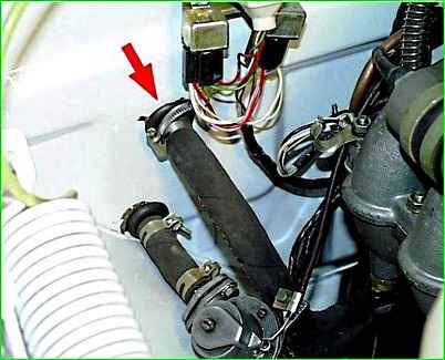
Loosen the clamp and remove the heater drain hose from the heater radiator fitting.
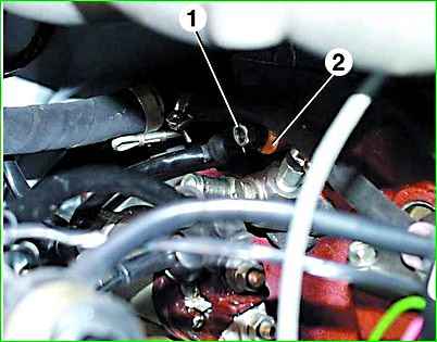
Unscrew nut 1, remove knock sensor 2 and move it along with the wire away from the engine.
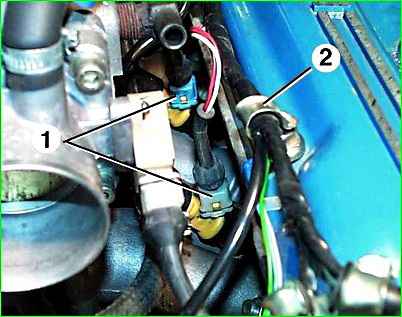
Disconnect connectors 1 from the injectors. Unbend the holders of 2 wire harnesses and remove the harness from the holders.
Place the wiring harness away from the engine.
Hook the engine onto the eyes on the exhaust manifold and generator bracket.
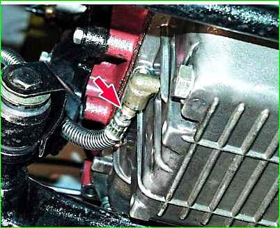
Unscrew the nut and disconnect the oil drain hose from the oil cooler from the fitting on the crankcase.
Remove the exhaust system.
Remove the gearbox.
Remove the clutch housing.
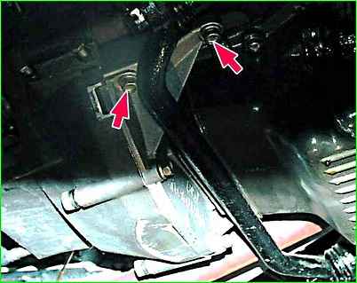
Remove two bolts on each side securing the clutch housing amplifier to the cylinder block.
Then lift the rear of the engine and remove the amplifier, bringing it out from behind the middle linkage of the steering link
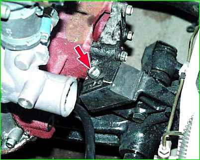
Unscrew the bolt securing the engine mount bracket to the mount on each side.
Check that all hoses and electrical wiring are disconnected from the engine.
Carefully lift out the engine.
Install the engine in reverse order. When installing the engine on the mounts, make sure that the mounting pins on the mounts fit into the holes on the engine brackets, and the bolt holes on the brackets and mounts should line up.
Distribution of work on the sides of the car
Work carried out from below the car:
- remove the driveshaft assembly;
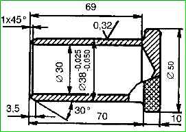
- - install the plug into the hole in the gearbox extension;
- - unscrew the nuts securing the rear engine mount to the cross member;
- - disconnect the cross member from the car frame and remove the cross member;
- - disconnect the speedometer shaft from the gearbox;
- - disconnect the bracket securing the exhaust pipes from the gearbox;
- - disconnect the exhaust pipes from the engine exhaust manifold;
- - disconnect the wires from the reverse light switch to the box ke gear;
- - unscrew the two bolts securing the working cylinder of the clutch release drive and disconnect the cylinder from the clutch housing.
Work carried out on the left side of the car:
- - disconnect from the ignition distributor the high and low voltage wires going to the ignition coil, the wires from the starter, from the pressure and emergency oil pressure sensors on the oil filter, from the coolant temperature indicator sensor on the thermostat body and the coolant overheating warning sensor in cylinder head cover;
- - disconnect the fuel line hose from the fuel pump; - unscrew the bolt securing the left cushion to the bracket on the engine.
Work carried out on the right side of the car:
- - disconnect the wires from the generator;
- - disconnect the warm and cold air intake hoses from the air filter, air intake pipes, heat shield of the exhaust pipe and remove them;
- - disconnect the crankcase ventilation hose from the air filter, rocker cover and remove it;
- - remove the cover and filter element of the air filter;
- - bend the whiskers of the lock washers and unscrew the nuts securing the air filter housing, carefully remove the nuts and lock washers, preventing them from getting into the engine;
- - remove the air filter housing with flange and gaskets, cover the carburetor with a clean napkin;
- - disconnect the wires from the carburetor;
- - disconnect the throttle valve drive cable and the air damper rod from the carburetor;
- - disconnect the fuel bypass hose from the carburetor;
- - disconnect the hoses from the solenoid valve of the forced idle economizer system;
- - disconnect the two heater hoses from the engine;
- - disconnect the coolant drain valve;
- - disconnect the vacuum brake booster hose from the intake pipe;
- - disconnect the ground wire;
- - unscrew the bolt securing the right cushion to the bracket on the engine.
Work carried out from the front:
- - remove the radiator grille by loosening the fastening bolts;
- - disconnect the hood lock cable;
- - unscrew the bolts and remove the top panel of the radiator trim;
- - having unscrewed the bolts, remove the lower fastening bar of the radiator trim;
- - disconnect the hoses from the expansion tank to the thermostat housing and the distribution pipe;
- - disconnect the hoses from the radiator and from the engine, remove the hoses;
- - unscrew the radiator mounting bolts and remove it.
Work carried out inside the body:
- - lift the rubber seal to the gear shift lever handle;
- - unscrew the lever mounting cap on the neck of the gearbox cover and pull the lever up;
- - close the hole in the neck with a clean napkin. Remove the engine assembly with clutch and gearbox.
Reinstalling the engine is done in the reverse order of removal.


