Main brake cylinder GAZ-2705 removal and repair
The main brake cylinder with two successive pistons 10 and 17 and a two-section reservoir 4 with sensor 6 for an emergency brake fluid level drop indicator is attached to the cover of the vacuum booster
The brake master cylinder creates pressure in two independent hydraulic circuits.
The volume of brake fluid between pistons 10 and 17 is used to operate the rear brake mechanisms, and the volume of fluid between piston 17 and the end of the plug 20 is used to operate the front brake mechanisms.
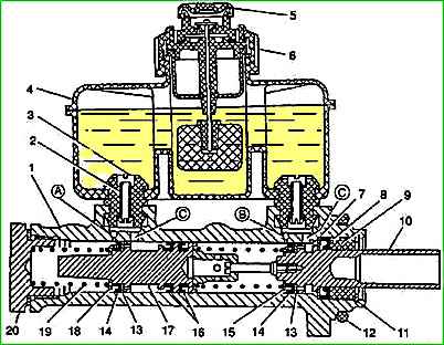
Main brake cylinder: 1 - body; 2 - tube; 3 - connecting sleeve; 4 - tank; 5 - protective cap; 6 - alarm sensor for emergency brake fluid level drop; 7 - thrust ring; 8 - outer cuff; 9 - guide sleeve; 10.17 - pistons; 11 - retaining ring; 12 - sealing ring; 13 - piston washer; 14.16 - cuffs; 15,18 - thrust washers; 19 – spring; 20 - plug; A, B - compensation holes; C - bypass holes
When braking, moving forward, the primary piston 10 and its cuff 15 cover the compensation hole “B” connecting the primary cavity of the master cylinder with the reservoir.
The spring installed between the pistons 10 and 17 is stronger than the spring 19 located between the piston 17 and the plug 20, therefore, simultaneously with the primary piston 10, the secondary piston 17 begins to move, covering with a cuff the compensation hole “A” connecting the secondary cavity of the cylinder with tank.
Further movement of the pistons is accompanied by an increase in pressure in the cavities, and, consequently, both brake circuits are activated.
When the force is removed from the brake pedal, the pistons return to their original position under the action of springs.
In this case, the compensation holes “A” and “B” open and the liquid in both cavities of the main cylinder communicates with the liquid in the tank, and the pressure in the circuits decreases to atmospheric pressure.
If the brake pedal is released abruptly, the pistons of the master cylinder quickly return to their original position and are ready for subsequent braking.
The rapid return of the pistons is ensured by the fact that when they return to their original position, a vacuum is created in the cavities of the main cylinder, under the influence of which liquid from the tank through the bypass holes C and the holes in the pistons, pressing washers 13 and the edges of the cuffs 14, enters the cavities of the main cylinder.
When the pistons reach their original position, excess fluid from each cavity will flow into the reservoir through compensation holes “A” and “B.”
If one of the drive circuits fails, fluid leaks from the cavity of the master cylinder connected to the faulty circuit.
If the rear circuit is faulty, then the piston 10 reaches the spring holder 16 and through it acts on the secondary piston 17, which creates pressure in the secondary cavity of the master cylinder and the front circuit.
If the front brake circuit fails, piston 17 acts on the end of plug 20, and piston 10, compressing the spring, displaces fluid from the primary cavity of the master cylinder into the circuit going to the brake mechanisms of the rear wheels.
If one of the drive circuits fails, the brake pedal travel increases, but fairly effective braking of the vehicle is ensured.
If the circuits are in good condition, the brake fluid level in the master cylinder reservoir should be between the MAX and MIN marks.
The gradual change in fluid level from MAX to MIN is associated with wear of the brake linings.
A sharp drop in the level of brake fluid in the reservoir indicates a violation of the tightness of the brake system.
At this point, the brake fluid level alarm is activated and a red lamp on the instrument cluster lights up.
In this case, fluid should be added only after the system’s tightness has been restored.
To check the serviceability of sensor 6 for an emergency drop in the liquid level in the tank, with the ignition on, press the central part of the protective cap 5 from above.
The lamp in the instrument cluster should light up.
Removing the master cylinder
To prevent dirt from getting into the main brake cylinder, thoroughly clean the connections of the pipes to the main brake cylinder.

Disconnect block 2 with wires from the level sensor brake fluid installed in the cap 1 of the master cylinder reservoir, and remove the cap.
Unscrew the mounting nuts 3 and disconnect the pipelines from the main cylinder.
Plug the pipeline holes.

Unscrew bolt 1 securing bracket 2 of the amplifier to the mudguard.
Unscrew the two nuts 3 securing the brake master cylinder 4 to the vacuum booster, remove the master cylinder with the bracket.
At the same time, make sure that the rubber seal between the cylinder and the vacuum booster does not fall out.
Turn over the master cylinder and drain the brake fluid from the reservoir into a container.
Then press the master cylinder piston several times to remove fluid from it.
Disassembling the master cylinder
Clamp the master cylinder in a vice and remove the rubber seal if it remains on the cylinder.
Remove the retaining ring while holding the piston.

Remove primary piston 1 assembly from the cylinder.
Remove the cylinder from the vice and, carefully tapping the end on a clean piece of wood, remove the secondary piston 7 and spring 6.
Remove guide sleeve 2, outer collar 3 and thrust ring 4 from the primary piston.
It is not recommended to unscrew the adjusting screw securing the spring holder 8 unless necessary.
Remove cuffs 5 from the secondary piston.

To replace connecting sleeves 2 of the tank, you must remove tank 1 and remove connecting sleeves 2 with plastic tubes from the main cylinder.

Inspection and troubleshooting of brake cylinder parts
Wash the master cylinder parts with clean brake fluid and dry.
The master cylinder mirror should not have marks, holes or areas of corrosion.
If these defects are present, the cylinder must be replaced.
There should be no mechanical damage on the threaded parts of the cylinder.
The master cylinder cuffs must be firm and elastic.
Torn, swollen and hardened cuffs, as well as those with marks on the working surfaces, must be replaced.
The end of the vacuum booster pusher and the mating surface of the primary piston should not have obvious signs of one-sided wear.
The surfaces of the pistons in contact with the cylinder bore should also not show signs of one-sided wear. Otherwise, it is recommended to replace the pistons.
Springs must have elastic properties.
Broken springs are replaced.
The threads of the tube tips must not have mechanical damage.
The fittings of the tips should not have cracks or signs of visible deformation.
Assembling the master cylinder
The brake master cylinder is assembled in the reverse order of disassembly.
Before assembly, it is necessary to lubricate the master cylinder parts with new brake fluid.
When installing the cuffs on the pistons, the working edges must be oriented as shown in the photo.

Install the cylinder in the reverse order of removal. After installation, it is necessary to bleed the brake system.
")

")
")
")
")
")
")
")