Removing the bridge from the vehicle must be done in the following sequence:
- - loosen the rear wheel nuts;
- - disconnect the driveshaft from the drive gear flange;
- - disconnect the parking brake drive cables from the equalizer;
- - disconnect the brake system hose, remove the brake pipes;
- - disconnect the lower end of the brake force regulator strut from the rear axle bracket;
- - place stands under the front wheels of the car, hang up the rear axle and place it on stands that ensure a stable position of the car;
- - unscrew the wheel nuts and remove the wheels;
- - disconnect the shock absorbers;
- - unscrew the nuts securing the spring ladders, remove the ladders and stabilizer brackets;
- - hang up the rear of the car using a crane beam and pull the bridge out from under the car.
Disassembling the bridge
Before disassembling the rear axle, you must unscrew the drain plug and drain the oil.
Disassemble the bridge in the following sequence:
- - unscrew the nuts securing the axle shafts and remove the axle shafts using dismantling bolts;
- - remove the axle shaft flange gaskets;
- - unscrew the outer nut of the hub bearing, remove the lock washer, unscrew the inner nut of the hub bearing;
- - remove the brake drum with hub assembly;
- - unscrew the bolts securing the brake to the crankcase flange and remove the brake assembly with cable and oil holder;
- - remove the rear crankcase cover and the cover gasket (for a one-piece rear axle);
- - unscrew the bolts securing the gearbox to the crankcase, remove the gearbox using the dismantling bolts and unscrew the filler plug (for a rear axle with a banjo beam);
- - unscrew the breather;
- - unscrew the bolts securing the locking plates of the differential bearing nuts, remove the locking plates;
- - unscrew the bolts securing the differential bearing covers, remove the covers, remove the bearing nuts and the differential assembly with the driven gear;
- - unscrew and unscrew the nut securing the drive gear flange, remove the flange and washer, remove the drive gear;
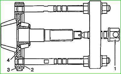
- - remove the inner ring of the rear bearing of the drive gear with a puller, as shown in the figure, so that the shoulders of the liner 4 fit tightly between the bearing race and the gear, the supports 2 should be compressed with bolts and nuts 3.
Press out the inner race of the bearing by rotating screw 1;
- - remove the adjusting ring;
- - press out the outer rings of the drive gear bearings.
Disassembling the differential
Disassembly of the differential must be done in the following order:
- - unscrew the driven gear mounting bolts, remove the driven gear;
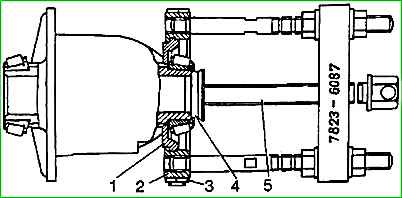
- - press the inner rings of the differential bearings using a puller assembly with liners, as shown in the figure
In order for the shoulders of the liners 1 to fit into the recesses on the differential box, the supports 2 should be compressed with bolts and nuts 3; press the bearing ring by rotating screw 5.
Inspection and control of bridge parts
Soak the parts of the disassembled rear axle (with the exception of bearings) in a washing solution, and then rinse and carefully inspect.
Replace parts with cracks.
If there are nicks, burrs and other irregularities on the machined surfaces of the parts, clean them to ensure a good fit of the mating parts.
In this case, special attention should be paid to the condition of the seating surfaces for the bearings.
Check for signs of scoring or signs of uneven wear on the bearing rings.
Check the condition of the roller ends.
Stepwise wear of the roller ends indicates insufficient pre-tightening of the bearings or misalignment of the rollers.
Inspect the teeth of the drive and driven gears for scoring or signs of excessive wear.
Worn gears and gears with scoring marks are unsuitable for further work.
Temporarily install the differential bearing caps and check that the nuts are screwed in.
The nuts must turn freely.
The ends of the nuts are in contact When equipped with bearings, they must be perpendicular to the thread axis. The runout of these ends relative to the thread axis should be no more than 0.02 mm.
The surface of the ends must be clean and smooth, and must not have step wear.
Make sure that the bearing caps are installed on the side on which they were machined.
The end of the drive gear flange in contact with the bearing must be smooth and should be ground if necessary.
The second end of the flange, in contact with the washer, must also be smooth; roughness and nicks at the ends of the flange weaken the tightening of the bearings.
The flange neck should not have nicks, scratches, excessive wear in the area of the cuff, and there should be no sharp edges on the lead-in chamfer.
The axle housing must not have any damage or residual deformation.
The surfaces of the bearing housings must be smooth, the threads for the differential bearing nuts must not be damaged.
It is necessary to remove all irregularities and burrs from the seating surfaces of the gearbox housing. Clean the oil channels.
Inspect the teeth and supporting surfaces of the gears of the axle shafts and satellites, the supporting and seating surfaces of the satellite boxes.
They should be smooth, without dents or burrs, and not have uneven wear or metal coating.
Wear of the side gear journal can cause increased noise from the rear axle.
Wear of the supporting surfaces or support washers causes an increase in the lateral play in the mesh of the differential gears and a violation of the correct meshing of the gears.
Check the tight fit of the inner rings of the differential bearings to the supporting surfaces of the differential pinion gear boxes - a 0.03 mm feeler gauge should not pass between the ring and the end of the box.
The inner rings should not rotate freely on the necks of the boxes.
Pay special attention to ensure that the contacting surfaces of both differential pinion gear boxes and the surface of the driven gear mounting flange are smooth and free of burrs.
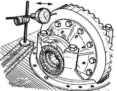
It is necessary to check the runout of the back of the driven gear, as shown in - for a one-piece rear axle (for a rear axle with a banjo beam - similarly, with the gearbox removed), the permissible runout is 0.08 mm.
If upon inspection it turns out that the runout exceeds the specified value, then we can assume that there is deformation of the driven gear, damage to the differential boxes or excessive wear of the bearings.
Unusable parts are repaired or replaced.
The axle housing should not have significant wear in the area of operation of the hub cuff, the surface under the cuff should be smooth, without scratches or nicks.
Differential assembly
Before assembly, all rubbing surfaces of the differential parts must be lubricated with the oil used in the axle.
Assemble the differential in the following order:
- - install the semi-axial gear washer and the semi-axial gear in one of the satellite boxes;
- - install satellites and satellite support washers on the satellite axis;
- - install the satellite axis with satellites and washers into the satellite box with the groove up;
- - assemble the second axis of the satellites, as indicated above;
- - install the second axis of the satellites with the groove down and install the second semi-axial gear and washer on top;
- - install the second satellite box so that the marks on the right and left boxes are opposite each other;
- - screw in and tighten the bolts securing the satellite boxes to a torque of 28-36 Nm (28-3.6 kgcm), having previously applied anasrobic sealant “Unigerm-6”, “Unigerm-9” or “Stopor-b” to the threads of the holes for the bolts ", 0.1 g in each hole.
The threads in the openings of the box and on the bolts must be dry and grease-free before applying sealant;
- - press the driven gear onto the left gearbox and secure it with bolts. Bolt tightening torque 68-75 Nm (6.8-7.5 kgcm).
Before tightening the bolts, apply the specified sealant, 0.2 g per hole, to the threads of the holes for the bolts in the gear, having previously degreased and dried the threads on the bolts and in the gear;
- - check the ease of rotation of the differential gears by rotating one of the axle gears using a splined mandrel with the differential housing stationary.
Rotation should be smooth, without jamming.
The torque required to rotate the differential gears should not be more than 15 Nm (1.5 kgcm).
When reassembling a rear axle with new pinion bearings or final drive gears, first adjust the pinion bearing preload and position (see Rear Axle Adjustment).
Assemble the bridge in the following order:
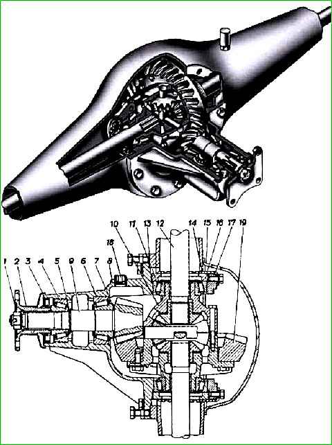
- - install adjusting ring 7 of the drive gear on the drive gear and press the inner ring of the rear bearing until it stops;
- - press the outer rings of the drive gear bearings into the crankcase;
- - install the drive gear into the outer ring of the rear bearing;
- - install the adjusting ring 5 bearings 6;
- - install the inner ring of the front drive gear bearing;
- - press the cuff of the 3rd drive gear flush with the end of the crankcase;
- - install flange 2, washer, tighten and cotter nut 1 of flange (see Adjusting the final drive);
- - install the differential with bearings into the crankcase, pressing their outer rings tightly;
- - install the adjusting nuts 16 of the differential bearings into the threaded hole of the crankcase as close as possible to the bearings and install the covers 17 of the differential bearings;
- - tighten the cover bolts with a torque that does not interfere with the rotation of the differential bearing adjusting nuts. Before tightening the bolts, apply Unigerm-6 or Unigerm-9 anaerobic sealant to the threads of the holes in the bridge housing.
The threads in the crankcase and on the bolts must be cleaned, degreased and dried;
- - adjust the preload of the differential bearings and the position of the driven gear (see Adjusting the preload of the differential bearings and the lateral clearance in the meshing of the final drive gears);
- - finally tighten the differential bearing cap bolts to a torque of 90-110 Nm (9-11 kgcm);
- - bolt the locking plates 14 nuts of the differential bearings;
- - apply sealing paste Un-25 to gasket 13 on both sides, after curing, install the gasket on the end of the crankcase;
- - install the gearbox into the axle housing and tighten its mounting bolts to a torque of 55-70 Nm (5.5-7.0 kgf m);
- - install brake assemblies and oil deflectors. The tightening torque of the oil deflector bolts is 14-18 Nm (1.4-1.8 kgcm), the brake mounting bolts are 50-62 Nm (5.0-6.2 kgcm);
- - install the right and left hubs with brake drum assemblies and adjust them;
- - install axle shaft gaskets on the hub studs;
- - insert the axle shafts and tighten the axle shaft nuts to a torque of 90-125 Nm (9.0-12.5 kgcm);
- - install and lock the bolts for dismantling the axle shafts with locknuts;
- - install the drain plug into the crankcase and screw in the breather;
- - fill the bridge with oil according to the lubrication chart through the filler hole in the cover and tighten the filler plug; Fill the hubs with the same oil by alternately tilting each side of the axle to a height of at least 200 mm;
- - check the noise level, heating and make sure there is no oil leakage in forward and reverse gear at a drive gear rotation speed of 16, 25, 50 s -1
Check the operation of the differential at a rotation speed of 25 s -1 (1500 min 1), alternately braking each of the axle shafts.
The total time for checking and running in the bridge is about 5 minutes. The check should be carried out with the oil heated to a temperature of 45-75°C and an excess pressure inside the bridge of 20-30 kPa (02-0.3 kgf/cm 2).
When assembling the rear axle, the dimensions of the mating parts of the rear axle should be taken into account.
Installing a bridge
Installation of the bridge on the vehicle must be done in the following order:
- - hang the rear of the car using a crane beam, start the axle mounted on a stand under the car, lower the car onto the bridge so that the spring pinch bolts fit into the holes in the spring pads;
- - install stepladders, stabilizer brackets, shock absorbers, tighten the nuts securing the stepladders;
- - install the wheels and tighten the wheel nuts;
- - raise the car, remove the stands from under the bridge;
- - install the brake pipes, connect the brake system hose and the lower end of the brake force regulator strut;
- - attach the parking brake drive cables to the equalizer;
- - attach the driveshaft to the drive gear flange;
- - finally tighten the wheel nuts;
- - good start the brake system.
")

")
")
")
")
")
")
")