The hydraulic pushers of the ZMZ-406, ZMZ-405 engines, made in the form of cylindrical pushers and located between the cam shaft and the valves, combine two functions: transmitting force from the cam shaft to the valves and eliminating gaps in their drive.
The operation of the hydraulic pusher is based on the principle of incompressibility of engine oil, which constantly fills the internal cavity of the hydraulic pusher during engine operation and moves its plunger when a gap appears in the valve drive.
This ensures constant contact of the pusher (valve drive lever) with the camshaft cam without play. Thanks to this, there is no need to adjust the valves during maintenance.
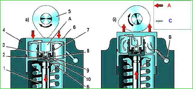
The operating principle of the hydraulic pusher is shown in the figure.
Oil under the pressure necessary for the operation of the hydraulic pusher is supplied to its internal cavities “A” and “B” from channel “B” of the engine lubrication system through a side hole in the pusher 6, made in the annular groove of its cylindrical surface.
When valve 1 is closed, pusher 6 (through plunger 7) and sleeve 9 are pressed respectively against the camshaft cam 5 and the end of the valve stem by the expanding force of spring 8.
The pressure in cavities “A” and “B” is the same, check valve 3 of the hydraulic compensator is pressed to the seat in plunger 7 by spring 2 - there are no gaps in the valve mechanism.
When the camshaft rotates, the cam 5 runs into the pusher 6, moving it and the plunger 7 associated with it.
The movement of plunger 7 in sleeve 9 leads to a sharp increase in pressure in cavity “B”.
Despite small oil leaks through the gap between the plunger and sleeve, pusher 6 and sleeve 9 move as one piece and open valve 1.
With further rotation of the camshaft, cam 5 reduces the pressure on pusher 6 and the oil pressure in cavity “B” becomes lower than in cavity “A”.
Check valve 3 opens and allows oil to pass from cavity “A”, connected to the engine oil line, into cavity “B”.
The pressure in cavity “B” increases, sleeve 9 and plunger 7, moving relative to each other, select a gap in the valve mechanism.
The oil pressure supplied to the hydraulic tappets is regulated by a special valve installed in the cylinder head.
Since after stopping the engine, oil flows from the channels coming from the oil pump into the oil sump, and the oil supply channels to the hydraulic tappets remain filled, after starting the engine, air plugs may form in the cavities of the latter.
To eliminate them, calibrated compensation holes are provided in the engine oil supply channels, which ensure automatic purging of the cavities of the hydraulic pushers.
In addition, compensation holes make it possible to slightly reduce the oil pressure entering the hydraulic tappets at high engine speeds, when the pressure in the cavity of the hydraulic tappet can become so high that its pusher, resting on the back of the camshaft cam, will slightly open the valve at the moment , not corresponding to the valve timing.
Almost all faults of hydraulic pushers are diagnosed by the characteristic noise emitted by the gas distribution mechanism at various engine operating modes.
Noise from valves can sometimes be eliminated by slightly turning the spring or valve around the longitudinal axis.
To do this, do the following.
- Rotate the crankshaft to a position where the valve making the noise begins to open slightly.
- Turn the spring a little and the valve will turn at the same time.
- Start the engine. If the noise continues, repeat steps 1 and 2.
- If turning the spring and valve does not give the desired result, check the condition of the spring and measure the gaps between the valve stems and guide bushings. Eliminate increased (compared to nominal) gaps.
If the valve and spring are in good condition, and the knocking of the valves is still heard when the engine is running, the hydraulic tappet is faulty. Replace it as follows.
- Disconnect the wire from the negative terminal of the battery.
- Remove the camshafts from the cylinder head supports (see Removal, troubleshooting and installation of camshafts).
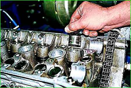
It is more convenient to remove the hydraulic pusher using a strong magnet or suction cup.
Before installation, place the new hydraulic tappet in a container with engine oil, press the hydraulic tappet sleeve several times to remove air and fill it with oil.
- Remove the hydraulic tappet from the cylinder head socket.
- Lubricate the socket in the cylinder head with engine oil and install the hydraulic pusher into the socket.
- The remaining hydraulic pushers are replaced in the same way.
- Install the camshaft and timing gear drive parts in the reverse order of removal.
Possible malfunctions of hydraulic pushers
Increased noise immediately after starting the engine
Oil leakage from part of the hydraulic tappets during parking - Noise that disappears a few seconds after starting the engine is not a sign of a malfunction, since oil leaked from part of the hydraulic tappets that were under the load of the valve springs of open valves (the oil supply channels remained open) , the deficiency of which is compensated at the beginning of engine operation
Intermittent noise at idle, disappearing as the crankshaft speed increases
Damage or wear of the check valve ball - Replace the hydraulic pushers
Contamination of the hydraulic pusher mechanism with wear products due to untimely oil changes or poor quality - Clean the mechanism parts from contamination. Use the oil recommended in the owner's manual
Increased noise during idling of a warm engine, disappearing at increased crankshaft speed and completely absent on a cold engine
Oil flows through the increased gap between the plunger and the hydraulic pusher sleeve - Replace the hydraulic compensator
Increased noise that occurs at high crankshaft speeds and disappears at low frequencies
Oil foaming when there is excess oil (above the “P” mark on the dipstick) in the oil sump due to agitation by the crankshaft.
The entry of an air-foam mixture into the hydraulic pusher disrupts its operation - Bring the oil level in the oil sump to the normal level
Air being sucked in by the oil pump when the oil level in the oil sump is too low - Bring the oil level to the normal level
Damage to the oil receiver due to deformation of the oil sump when hitting a road obstacle - Repair or replace the defective parts
Continuous noise of one or more valves, independent of crankshaft speed
The appearance of a gap between the pusher and the camshaft cam due to damage to the hydraulic compensator - After removing the valve mechanism cover, install the camshaft cams one by one with the protrusions upward and check for the presence of a gap between the pushers and the cams. While pressing (for example, with a wooden wedge) the pusher of the hydraulic compensator being tested, compare the speed of its movement with the speed of the others.
If there is a gap or increased movement speed, replace the compensator.
After starting a cold engine, a knocking sound may appear from the valve lifters, which should disappear as the engine warms up to a coolant temperature of plus 80-90 °C.
If the knocking noise does not disappear more than 30 minutes after reaching the specified temperature, it is necessary to check the serviceability of the hydraulic pushers as follows.
A knock that appears when starting a cold engine, repeatedly starting the engine (with several unsuccessful starts), starting the engine after a long stay and disappearing subsequently when the engine warms up is not a malfunction of the hydraulic pusher.
This knocking sound of the hydraulic pushers is caused by the suction of air into the chamber of the hydraulic compensator of the hydraulic pusher, which leads to a loss of its rigidity and the operation of the valve drive with shock.
To remove air, it is recommended to perform the following steps:
- - start and warm up the engine to operating temperature. For 3 - 4 minutes, set the engine operating mode at a constant speed of 2500 rpm or at a varying speed range of 2000-3000 rpm, then listen to the engine idling for 15...30 seconds. In 90% of cases the knocking should stop
- - if the knocking does not stop, repeat the cycle up to 5 times;
- - if the knocking does not stop after the above work, work for another 15 minutes at a speed of 2000-3000 rpm, then listen to the engine idling for 15-30 seconds.
If the knocking does not go away after 5 cycles plus 15 minutes of engine operation, the following work must be done:
- - using a stethoscope (or other device, amplifying the sound) localize the source of the knock;
- - remove the valve cover;
- - slowly turning the camshafts, set all hydraulic tappets one by one to the “valve fully closed” position and in this position check them by applying force to the working end along the axis of movement:
a) elastic elasticity upon short-term application of a force of about 10 N (1 kgf) indicates the presence of air in the high-pressure chamber of the compensator;
b) the appearance of a gap between the working end of the hydraulic pusher and the cam when a load of about 20-30 N (2-3 kgf) is applied for a period of 10-15 seconds and disappears after the load is removed, indicates a leak in the check valve of the compensator or wear of the plunger pair of the hydraulic compensator ;
c) the presence of a gap between the working end and the camshaft cam indicates wedging of the compensator
Replace hydraulic pushers with the above symptoms.
In the absence of the listed comments, remove all hydraulic tappets from the cylinder head sockets and check the appearance of the hydraulic tappets and camshaft cams for rough scratches, cracks, signs of wear, foreign particles, and contamination.
Check the oil supply to the hydraulic tappets, the running-in at the end of the hydraulic tappet and the rotation in the seat.
Parts that have fatal defects must be replaced. Check the settlement of the valve springs under load (see article - “Cylinder Head”).
Replace the hydraulic pushers located in the areas identified by the stethoscope.
")

")
")
")
")
")
")
")