The rear axle bearings, lateral clearance and the position of the contact patch in the engagement of the main pair are adjusted at the factory, and, as a rule, they do not require adjustment during operation
Their adjustment is necessary only after rebuilding the bridge and replacing parts, as well as when the bearings are worn heavily.
The lateral clearance in the main gear engagement, which has increased due to tooth wear, is not reduced by adjustment, as this leads to a disruption of the engagement and, as a consequence, to increased noise of the rear axle or tooth breakage.
Backlash in tapered bearings is eliminated without disturbing the relative position of the driven and driving gears.
Adjusting the drive gear bearing preload
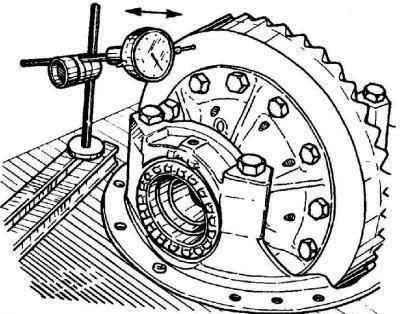
The need for bearing adjustment can be determined by the presence of axial play in the drive gear.
Axial play is measured with the driveshaft disconnected using an indicator with a division value of no more than 001 mm when moving the flange in the axial direction.
The indicator leg should rest against the end of the flange parallel to the axis of the drive gear.
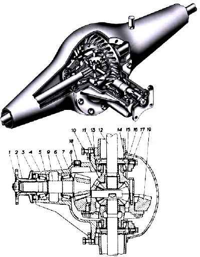
Axial play in the drive gear bearings should be eliminated by adjusting the preload. The preload is adjusted by selecting the thickness of the adjusting ring 5.
Adjustment must be done as follows:
- - unscrew and unscrew nut 1, remove flange 2, oil seal 2 and inner ring of bearing 4;
- - replace the adjusting ring 5 with a new one, the thickness of which should be less than the value of the axial play being replaced plus an additional 005 mm for a vehicle mileage of less than 1000 km or 001 mm for a vehicle mileage of more than 10,000 km;
- - put in place the inner ring of the bearing, a new oil seal, flange and tighten the nut to a torque of 160-200 Nm (16-20 kg/cm), then check the ease of rotation of the drive gear.
If more force is required to rotate the drive gear than it was before adjustment, then it is necessary to replace the adjusting ring, increasing its thickness by 001-002 mm.
After adjusting the bearing preload, it is necessary to tighten the nut to a torque of 160-200 Nm (16-20 kg/cm) until the slot in the nut coincides with the hole for the cotter pin.
The nut to match the hole for the cotter pin with the slot of the nut must only be tightened, since otherwise, due to insufficient tightening, the inner ring of the outer bearing may rotate, wear out the adjusting ring, and, as a result, increase the axial play of the bearings.
When tightening the flange nut, it is necessary to rotate the drive gear to ensure proper installation of the rollers in the bearings.
After adjustment, it is necessary to check the heating of the bearings after driving the car at a speed of 60-70 km/h for 20-30 minutes
In this case, the heating of the crankcase neck should not exceed 95° C (water that gets onto the neck should not boil).
If the temperature is excessive, reduce the preload.
Adjust the preload when replacing the bearings of the drive gear and final drive gear in the following order:
- - it is necessary to adjust the position of the drive gear by selecting the adjusting ring 7 of the gears and the end of the drive gear adjacent to the adjusting ring 7;
- - by selecting adjusting ring 5, adjust the preload of the drive gear bearings.
With proper adjustment, the moment of resistance to rotation of the drive gear should be in the range of 150-200 Nm (15-10 kgf/cm) for new bearings or 70-100 Nm (7-10 kgf/cm) for used bearings.
If the moment of resistance to rotation of the bearings is within the normal range, it is necessary to tighten the nut, otherwise the adjustment should be repeated.
In this case, if the moment of resistance to rotation is less than required, it is necessary to reduce the thickness of the adjusting ring, and if it is greater, it is necessary to select a ring of greater thickness.
After adjusting the bearing preload, it is necessary to install the differential assembly into the axle and adjust the differential bearing preload and the lateral clearance in the meshing of the final drive gears.
Adjusting the preload of the differential bearings and the lateral clearance in the mesh of the gears and final drive
Adjustment without replacing bearings
To adjust the bearings you need:
- - remove the axle shafts, crankcase cover and cover gasket (for a one-piece rear axle);
- - remove the axle shafts and remove the gearbox from the axle housing (for the rear axle with a banjo beam);
- - with the locking plates 14 removed (see) and the differential bearing covers 17 loosened, use adjusting nuts 16 to set the axial clearance of 0.01 mm in the differential bearings
- - install an indicator and check the lateral clearance in the gear mesh, which should be within 0.15-0.25mm. Check at least six points, turning the gear each time;
- - loosen the adjusting nut on the side of the driven gear to increase the lateral clearance and tighten the opposite nut by the same number of grooves. To reduce the side clearance, these operations are performed in reverse order;
- - adjust the preload value by compressing the bearings in the axial direction
By 0.1 mm when the car's mileage is less than 1000 km.
By 0.05mm with a mileage of more than 10,000 km.
Control by the angle of rotation of the adjusting nut. Turning one nut towards the other by the width of the groove corresponds to compression of the bearings by 0.05 mm;
- - tighten the differential bearing cap bolts and check the lateral clearance of the final drive gear teeth;
- - bolt the locking plates to the bearing caps;
- - install the gearbox into the axle housing;
- - install axle shafts.
Adjustment when replacing bearings
To adjust the bearings you need:
- - remove the axle shafts, crankcase cover and cover gasket (for a one-piece rear axle);
- - remove the axle shafts and remove the gearbox from the crankcase (for the rear axle with a banjo beam);
- - remove the locking plates 14 from the differential bearing covers 17;
- - unscrew the bolts securing the covers, remove the covers, remove the differential and adjusting nuts 16;
- - measure the residual friction moment of the drive gear bearings with a dynamometer
- - press out the inner rings of the bearings from the differential box and press on new ones;
- - put the differential in place with new bearings, pressing their outer rings tightly;
- - insert adjusting nuts 16 into the threaded part of the rear axle housing, as close as possible to the bearings, and install covers 17 according to the markings on the bearing covers and on the rear axle housing;
- - secure the bearing caps with bolts with a force that does not interfere with screwing in the adjusting nuts 16 (the holes in the crankcase for the bolts must first be lubricated with anaerobic sealant);
- - tighten the bearings with adjusting nuts until a slight preload is obtained.
When prestressing the bearings, the driven gear must be turned several revolutions in one direction, then in the other direction for proper installation of the rollers in the bearings;
- - by alternately tightening the adjusting nuts of the differential bearings, achieve an increase in the moment of resistance to rotation of the drive gear by 150-300 Nm (15-30 kgf/cm) relative to the residual moment of resistance to rotation, measured after removing the differential;
- - from the side of the driven gear and tighten the nut on the side of the drive gear by the same number of grooves to maintain the preload of the bearings; to reduce the side clearance, these operations are performed in the reverse order;
- - rotation of the adjusting nuts must be completed by tightening.
For example, if you need to loosen the nut by one groove, then you should loosen it by two, and then tighten it by one groove. This ensures that the nut is in contact with the outer ring of the bearing and that the ring does not move during operation;
- - finally tighten the bolts securing the bearing caps, secure the locking plates on the bearing caps with bolts;
- - install the gasket and rear cover (for a one-piece rear axle);
- - install the gearbox into the axle housing (for the rear axle with a banjo beam);
- - install axle shafts.
Checking the engagement using the contact patch
After final assembly and adjustment of the axle gearbox, the gear engagement should be checked. To do this, you need to paint the teeth with paint.
It should be taken into account that very liquid paint spreads and stains the surface of the teeth; too thick paint cannot be squeezed out of the spaces between the teeth.
By slowing down the driven gear, rotate the drive gear in both directions until a clear contact patch is identified.
Obtaining the correct tooth contact pattern completes the check of gear installation and lateral clearance in mesh.
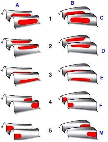
The side clearance must be within the above limits. The pictures show typical contact spots on the teeth of the rear axle final drive driven gear.
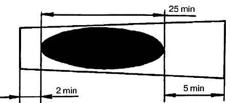
The contact patch on both sides of the driven gear tooth should be located as shown in Figure 4
If during the adjustment process there is a need to move the drive gear, this can be achieved by changing the thickness of the set of shims installed between the end of the gear and the end of the inner ring of the rear bearing of the drive gear.
When the side clearance changes, the location of the contact patch changes. The contact in this case moves as follows:
- to reduce the side clearance, the driven gear moves towards the drive gear, the contact patch on the working (convex) side of the tooth moves slightly lower and closer to the narrow end of the tooth;
- to increase the lateral clearance, the driven gear is moved away from the driving gear:
- - on the working side of the tooth, the contact patch moves slightly higher and closer to the wide end of the tooth;
- - on the non-working side of the tooth, the contact patch moves slightly higher and closer to the wide end of the tooth;
3. When the drive gear approaches the driven gear:
- - the contact patch on the working side moves lower and closer to the narrow end of the tooth;
- - the contact patch on the non-working side moves lower and closer to the wide end of the tooth;
4. When moving the drive gear away from the driven gear:
- - the contact patch on the working side of the tooth moves to the top of the tooth and to its wide end;
- - on the non-working side of the tooth, the contact patch moves to the top of the tooth and moves slightly towards its narrow end.
")

")
")
")
")
")
")
")