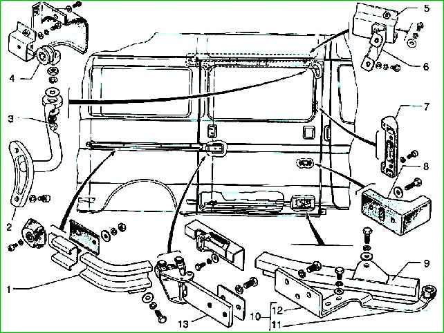
To replace the bearing assembly of the upper 5, middle 1 and lower 9 guides, the middle mechanism 13, the side door must be removed.
For this:
- - remove the plug from the middle guide;
- - unscrew the buffer;
- - move the door to the cutout in the upper guide and remove the roller from engagement with it (to avoid damage to the body and door, this operation must be performed by two people);
- - tilt the door to disengage the roller of the lower mechanism;
- - disengage the middle guide mechanism by moving the side door along the middle guide until the mechanism rollers disengage and remove the door.
When replacing the middle guide, it is necessary to remove the side panel trim, and when replacing its mechanism, the door trim must be removed.
Install the door in reverse order.
Install the door trim after adjusting the door installation.
The side door installation adjustments are designed for reliable operation of its mechanisms that ensure movement, closing - opening and reliable locking of the door.
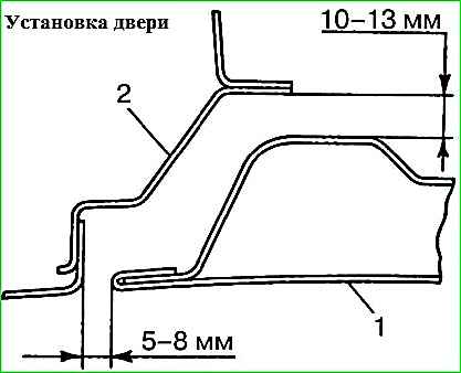
The correct installation of the door is determined by the gaps of the door (in the closed position) relative to the side
- - along the door opening 5-8 mm;
- - along the internal rebate gap between the sidewall and the door 10-13 mm.
The movement of the door along the top 5, middle 1 and bottom 9 guides is ensured by the top 2, middle 13 and bottom 10 mechanisms.
Adjustment of the door in the vertical direction is carried out by moving the roller with carriage 4 of the upper mechanism 2 along the thread of axis 3, as well as the middle 13 and lower 10 mechanisms up or down.
Adjustment of the door in the direction of travel is carried out by shifting the axis 3 of the carriage of the upper mechanism 2 in the lever head, as well as the middle 13 and lower 10 mechanisms forward or backward.
Adjustment of the door in depth (recession - protrusion) is carried out by shifting axis 3 of the carriage of the upper mechanism (if necessary, it is possible to place a washer with a diameter of 24-30 mm with a hole with a diameter of 6.5-8 mm and a thickness of 1-2 mm between the support of the upper guide and the guide itself 5), as well as moving the lower lever 11 with the roller relative to the support 12 and the support 12 itself relative to the door.
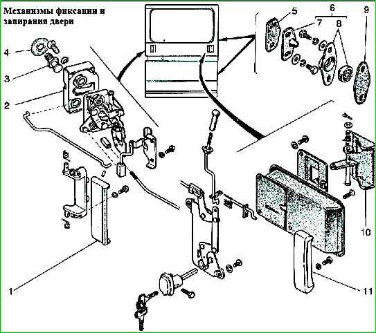
Fixing and locking the door in the sidewall opening is ensured by:
- - along the front end of the door with two latches 7;
- - at the rear end of the door with a spike 3 and a locking mechanism 2.
Adjustment along the front end of the door is carried out by moving the housing 9 of the latch in the vertical direction of the tenon 8 of the latch in depth and installing shims 6 under the tenon 8 and shims 10 under the housing 9 of the latch.
To determine the number of spacers:
- - connect the body 9 of the latch tightly with the pin 8 of the latch (with the door open);
- - close the door;
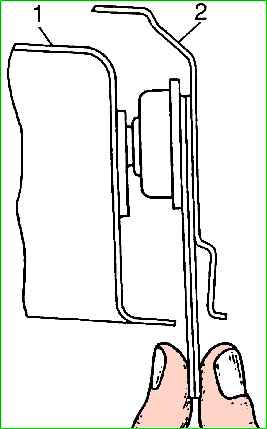
- - use shims 10 to determine the size of the gap between the retainer body and the sidewall, using the gap between door 1 and sidewall 2 for access;
- - open the door;
- - install evenly (the difference is no more than 1 pc.) spacers 6 and 10 under the tenon and the latch body.
Adjust the engagement of the tenon 3 with the locking mechanism 2 at the rear end by moving the tenon 3 on the sidewall (you can additionally place a washer 4 under the tenon, but no more than 2 pieces).
After all necessary adjustments have been made, it is not possible to remove the door without using the cutout in the top guide.
In the closed position, the door must be tightly fixed in the front opening on two clamps 7 and locked with a locking mechanism 2 on a spike 3 in the rear opening of the sidewall.
The moving parts of the mechanisms (bearing of the upper roller 4, threads of the axis 3 of the upper carriage, the axes of the guide rollers of the middle mechanism 13) must be lubricated with Litol-24, LITA or CIATIM-201 grease.
It is strictly prohibited vehicle operation:
- - with doors open or locked only by the safety tooth of the lock cam;
- - when the roller of the lever 11 of the lower mechanism disengages from the flange of the lower guide 9;
- - when the tenon 8 is not tightly seated in the body 9 of the clamp.
Possible malfunctions of mechanisms
Fault - Remedy
The door comes out of contact with the middle track
The axis of the guide rollers is broken or bent and one of the rollers is missing - Replace the middle guide mechanism
The door does not close well in the extreme position
Sticking of guide rollers in the middle guide - Replace the middle guide
Uneven gaps between the side of the body and the door
The door installation adjustment was not performed correctly - Make the necessary adjustments
The front end of the side door does not fit against the side
The latch pin is broken - Replace the latch pin and adjust its position
You can also look at the article - “Removing, installing and adjusting the sliding door of a Gazelle car”